Diagnostics Using the User Program
10-19
DP/PA Link and Y Link Bus Couplings
A5E00193841-011
10.4.2 Solution with STEP 7
Call of the SFC 13
Call up the OB 1 SFC 13 (DPNRM_DG) in OB 1 and thereby read out the
diagnostic data from the IM 157.
Table 10-10Call of the SFC 13 (DPNRM_DG) in the OB 1
STL Explanation
CALL SFC 13
REQ :=TRUE
LADDR :=W#16#3FE
RET_VAL :=MW0
RECORD :=P#DB10.DBX 0.0 BYTE 190
BUSY :=M2.0
//Request to read the diagnostic data
//Diagnostic address of the IM 157
//RET_VAL of SFC 13
//Data mailbox for the diagnosis in DB10
//Read operation runs through several OB1
cycles
With this call, the diagnostic data are stored in DB 10.
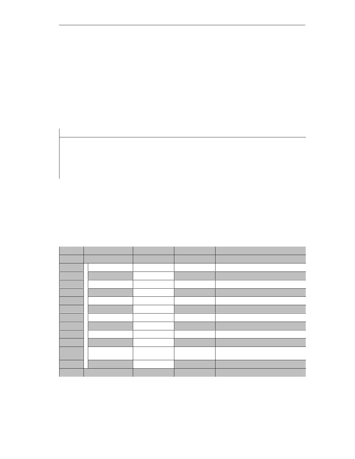
Appearance of DB 10
Define the following structure for DB 10:
Address Name Type Initial value Comment
0.0 STRUCT
+0.0 Norm_Diag ARRAY [1..6] Standard diagnosis
*1.0 BYTE
+6.0 Kenn_Diag ARRAY[1..31] Module diagnosis
*1.0 BYTE
+38.0 Modul_Diag ARRAY[1..63] Module status
*1.0 BYTE
+102.0 Status_Message ARRAY[1..60] Status message
*1.0 BYTE
+162.0 H_Status ARRAY [1..8] H Status
*1.0 BYTE
+170.0 Interrupt sec-
tion
ARRAY [1..20] Interrupts
*1.0 BYTE
=190.0 END_STRUCT

 Loading...


