Diagnostics Using LEDs
9-6
DP/PA Link and Y Link Bus Couplings
A5E00193841-011
9.3 LED displays of the Y coupler
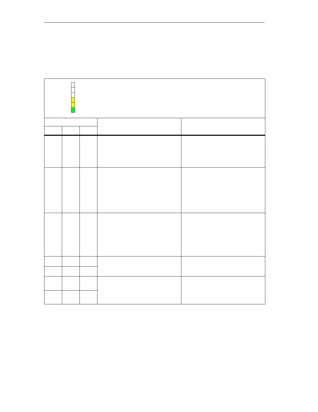
Table 9-3 Status messages of the Y coupler
DP 1
ON
DP 2
DP 1: Bus monitoring of the internal PROFIBUS-DP (yellow)
DP 2: Bus monitoring of the underlying PROFIBUS-DP (yellow)
ON: 24V power supply for Y coupler (green)
LEDs Meaning What to do
BF 1 BF 2 ON
Off Off Off No voltage present at Y coupler. Switch on the IM 157 power supply.
If the ON LED does not light up when
the IM 157 power supply is switched
on: Replace the IM 157 due to a faulty
internal power supply.
Off Off On Voltage at Y coupler. The Y coupler is
ready for operation. There is no data
exchange between the internal and
underlying DP master system.
Check whether the bus connector
is properly connected.
Check if the bus cable to the
underlying DP master system has
been interrupted.
Check whether the bus modules
are properly connected.
On Off On Frames from the underlying DP
master system are not being received,
e. g.:
The connection to the underlying
DP master system is interrupted.
DP slaves are not responding.
Check whether the underlying DP
master system is properly
connected (the bus connector is
attached and the two bus
terminating resistors are
connected in if necessary).
Check the connected DP slaves.
* On On Data is being exchanged between the –
On * On
internal and underlying DP master
systems (at a high transmission rate).
* Flash
es
On Data is being exchanged between the
internal and underlying DP master
–
Flash
es
*
systems (at a low transmission rate).
*
Not applicable

 Loading...


