Diagnostics Using LEDs
9-2
DP/PA Link and Y Link Bus Couplings
A5E00193841-011
9.1 LED displays of the IM 157
PA field devices and DP slaves communicate on the same basis. Therefore, we
will use the following simplified terminology in this section:
“Slaves” stands for both the PA field devices and the underlying DP slaves.
“Underlying master system” stands for both the PA master system and the
underlying DP master system.
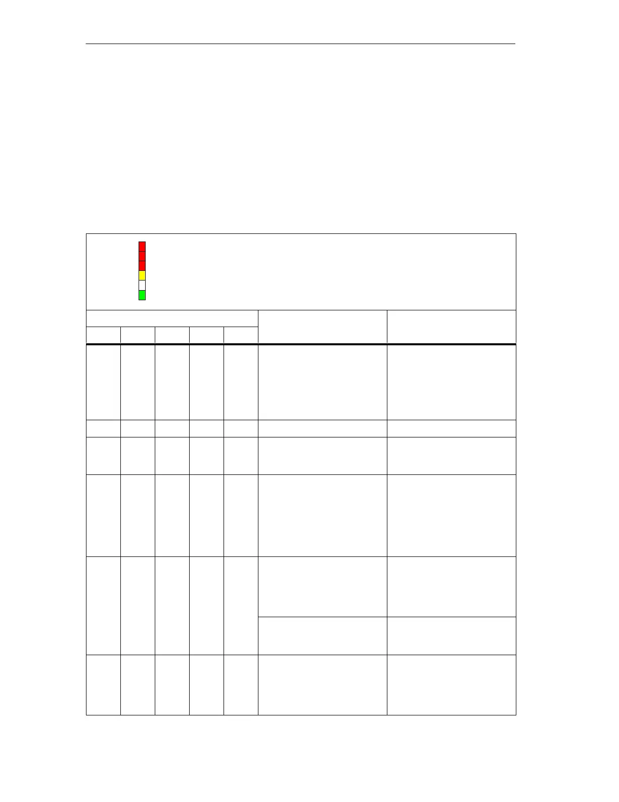
Table 9-1 Status and error messages of the IM 157
BF 1
ON
BF 2
SF: Group error (red)
BF 1: Bus fault in higher level PROFIBUS-DP (red)
BF 2: Bus fault in underlying PROFIBUS (red)
ACT: IM 157 has an active channel (yellow)
ON: 24V power supply IM 157 (green)
SF
ACT
LEDs Meaning What to do
SF BF 1 BF 2 ACT ON
Off Off Off Off Off No voltage present at
IM 157.
Applied supply voltage is
not within permissible
range.
Hardware error in IM 157
Switch the power supply
module on.
Check the applied
voltage.
Replace the IM 157.
* * * * On Voltage present at IM 157. –
On On On On On All LEDs come on for approxi-
mately 1 second. The IM 157
is starting up.
–
Flash
es
(quickly)
Flash
es
(quickly)
Flash
es
(quickly)
Flash
es
(quickly)
Flash
es
(quickly)
Error within IM 157. Set the DIP switch of the
IM 157 to address 127 (see
Chapter 6.4) and read out by-
tes 102 to 117 from the diag-
nostic frame. Contact your
Siemens partner and have
this information on hand.
Off Off Off Off On In non-redundant operation:
The IM 157 is engaged in
data exchange with the DP
master and the underlying
slaves.
–
Redundant operation:
The IM 157 is passive and
can be switched over.
–
Off Off Off On On Non-redundant operation
only: The IM 157 is active and
engaged in data exchange
with the DP master and the
underlying slaves.
–

 Loading...


