Diagnostics Using LEDs
9-3
DP/PA Link and Y Link Bus Couplings
A5E00193841-011
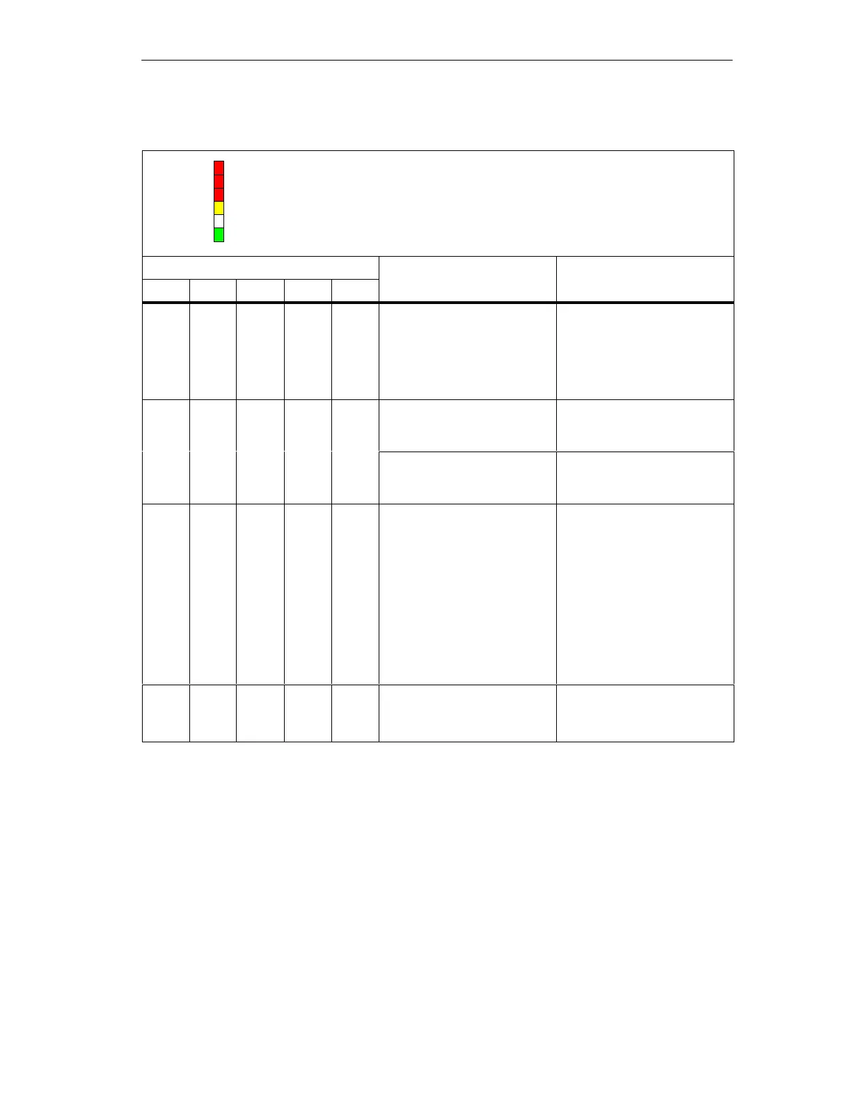
Table 9-1 Status and error messages of the IM 157
BF 1
ON
BF 2
SF: Group error (red)
BF 1: Bus fault in higher level PROFIBUS-DP (red)
BF 2: Bus fault in underlying PROFIBUS (red)
ACT: IM 157 has an active channel (yellow)
ON: 24V power supply IM 157 (green)
SF
ACT
LEDs What to doMeaning
SF
What to doMeaning
ONACTBF 2BF 1
Off Off Flash
es
(quickly)
* On Power-up delay is active on
the IM 157.
If the IM 157 does not com-
plete startup within 20 sec-
onds, check in the configura-
tion whether start-up is en-
abled for desired layout ac-
tual layout.
* Off On Off On Non-redundant operation:
IM 157 configuration missing
Check whether the CPU or
the DP master are in RUN
mode.
Redundant operation:
The IM 157 is passive and
cannot be switched over yet.
Check whether the H system
is in redundancy mode.**
* On * Off On No connection to the DP
master. Possible causes:
The bus communication
to the IM 157 has been
interrupted.
The DP master is not in
operation.
Check that the bus
connector is correctly
inserted.
Check if the
interconnecting cable to
the DP master has been
interrupted.
Switch the 24V DC switch
on the power supply
module off and then on
again.
* Flash
es
* Off On There is no data exchange
between the DP master and
the IM 157.
Check the configuration.
Check the PROFIBUS
address.
 Loading...


