Installation
3-6
DP/PA Link and Y Link Bus Couplings
A5E00193841-011
3.4 Installing the DP/PA link for redundant operation
Configuration with bus modules
For redundant operation, the DP/PA link must configured with bus modules.
Required components
Rail for configuration with active bus modules (”Rail for module change during
operation”)
2 x IM 157
BM IM/IM bus module
1 to 5 x DP/PA coupler
One BM DP/PA coupler bus module for each DP/PA coupler
You can find the order numbers for these components in Appendix D.
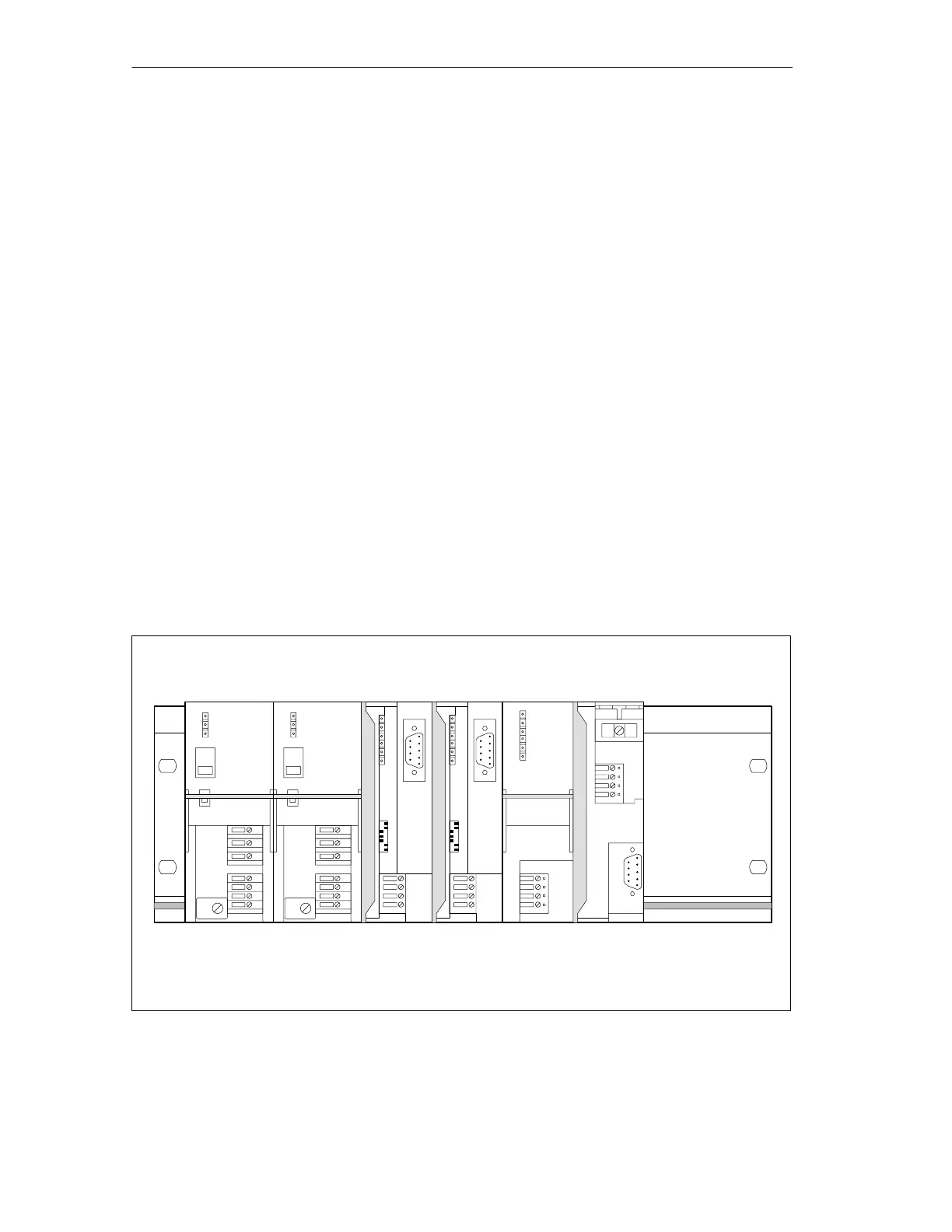
Typical configuration
The figure below shows the typical configuration of a DP/PA link for redundant
operation with two power supply modules. The front doors are open.
PS 307 PS 307 IM 157 IM 157 DP/PA coupler
BM IM/IM
(not visible)
BM DP/PA coupler
(not visible)
Rail
Figure 3-2 Typical configuration of the DP/PA link for redundancy operation

 Loading...


