Diagnostics Using the User Program
10-10
DP/PA Link and Y Link Bus Couplings
A5E00193841-011
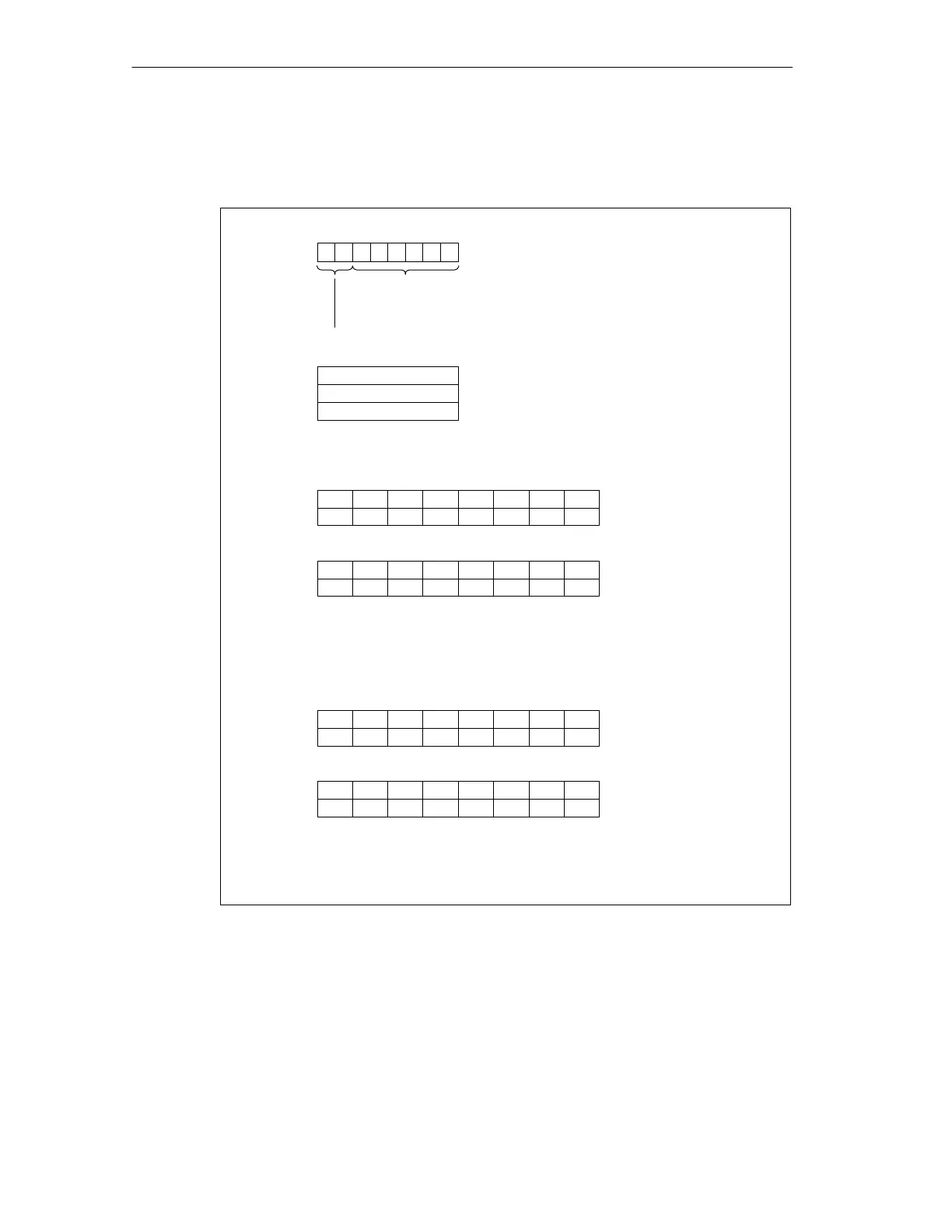
Structure of the status message
The status message consists of 60 bytes.
Byte x
Bit no.
Length of the diagnostic blockincluding byte x
(= 60 bytes)
Code for station diagnosis
7
6543210
00111100
Byte x+1 81
H
Status type: status message
Byte x+2
Not applicable
Byte x+3 Not applicable
If the bit is set, this indicates that the slave with the corresponding address
reported a diagnosis.
Byte x+4
Byte x+18
.
.
Bit no.76543210
Addresses 3 to 7
.
.
.
.
.
.
Addresses 112 to 119
76543–––
Slaves that have reported diagnosis
119 118 117 116 115 114 113 112
If the bit is set, this indicates that the slave with the corresponding address
is engaged in data exchange with the IM 157.
Byte x+20
Byte x+35
.
.
Slaves that are engaged in data exchange with the IM 157
Continued overleaf
Byte x+5
Addresses 8 to 15
Byte x+19 Addresses 120 to 125––125 124 123 122 121 120
15 14 13 12 11 10 9 8
Bit no.76543210
Addresses 3 to 7
.
.
.
.
.
.
Addresses 112 to 119
76543–––
119 118 117 116 115 114 113 112
Addresses 8 to 15
Addresses 120 to 125––125 124 123 122 121 120
15 14 13 12 11 10 9 8Byte x+21
Byte x+34
Figure 10-5 Structure of the status message
Start address x is 100 for both S7 standard operation and redundant operation; in
DP standard master operation, it is dependent on which diagnostic blocks are
present (see Table 10-2).

 Loading...


