Diagnostics Using the User Program
10-7
DP/PA Link and Y Link Bus Couplings
A5E00193841-011
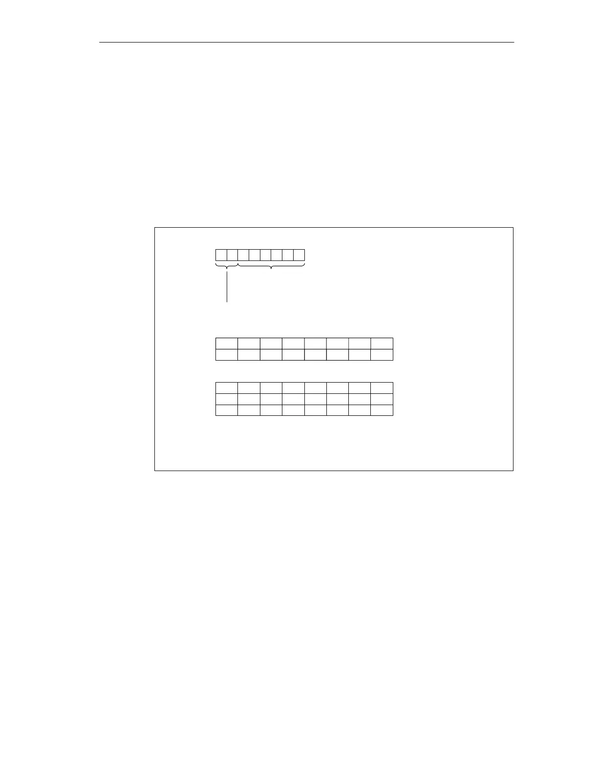
Structure of the module diagnosis
The module diagnosis comprises 31 bytes.
Each slave slot occupies one bit. The slaves are arranged in ascending order by
their PROFIBUS addresses.
A bit is set if:
the corresponding slave for the respective slot delivers a module diagnosis, or
the corresponding configured slave is not engaged in data exchange with the
DP master.
Byte 6
The set bit indicates that a slave either reported a diagnosis for the
respective slot or failed.
Bit no.
Length of the diagnostic blockincluding byte 6
(= 31 bytes)
Code for module diagnosis
Byte 7
Byte 8
7
Byte 34
Byte 35
Byte 36
.
.
6543210
01011111
Bit no.76543210
Slots 1 to 876543218
15 14 13 12 11 10 916 Slots 9 to 16
.
.
.
.
.
.
Slots 217 to 224223 222 221 220 219 218 217224
Slots 225 to 232231 230 229 228 227 226 225232
Slots 233 to 236236 235 234 233
Figure 10-3 Structure of the module diagnosis

 Loading...


