Fundamentals of PROFIBUS-PA
A-3
DP/PA Link and Y Link Bus Couplings
A5E00193841-011
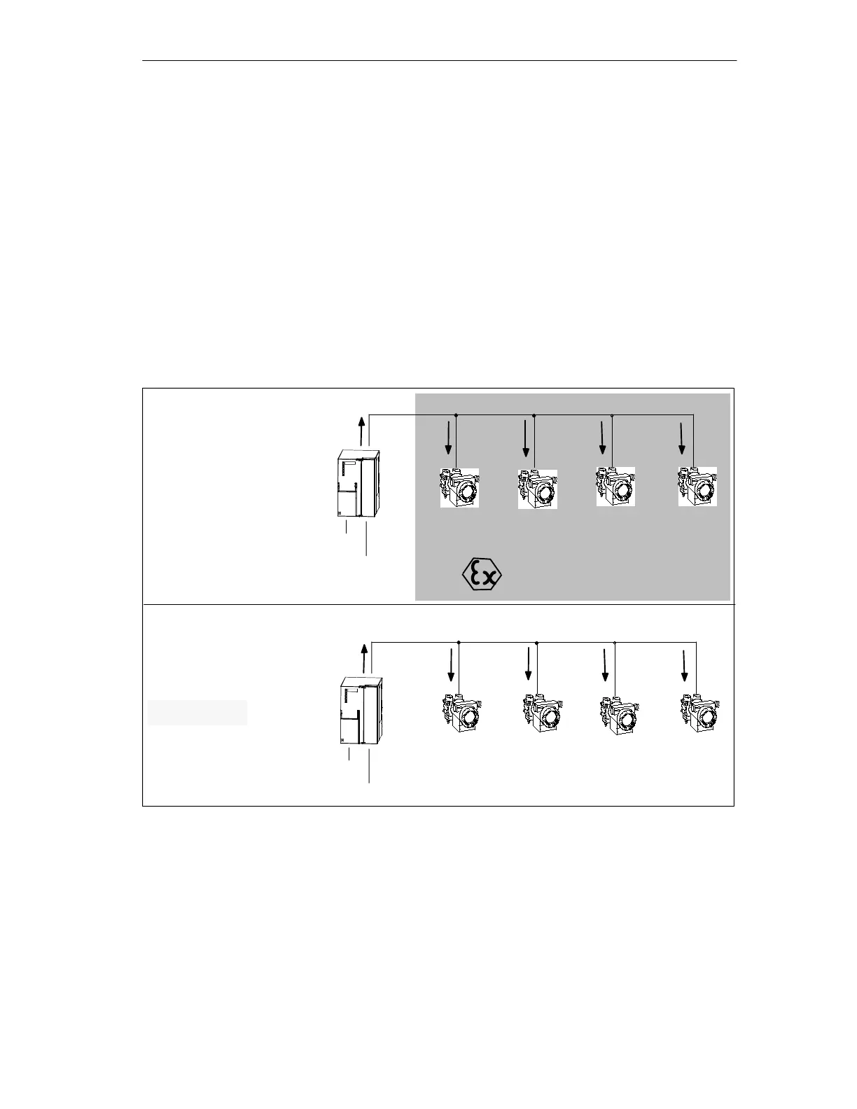
A.2 Field device supply via PROFIBUS-PA
Operating principle
When the DP/PA link coupler is used, the field devices can be supplied via the data
line of PROFIBUS-PA.
Structure
The total current of all the field devices must not exceed the maximum output
current of the DP/PA coupler. The maximum output current thus limits the number
of field devices that can be connected to PROFIBUS-PA.
PROFIBUS-DP
PROFIBUS-PA
I
max
.
I
1
I
2
I
3...
...I
m
I
max
x 400 mA
24 VDC
Field device
1
Field device
2
Field device
3...
Field device
...m
DP/PA coupler
6ES7 157-0AC80-0XA0
PROFIBUS-DP
PROFIBUS-PA
I
max
.
I
1
I
2
I
3...
...I
n
24 VDC
Explosion-proof area
Field device
1
Field device
2
Field device
3...
Field device
...n
I
max
x 110 mA
DP/PA coupler Ex [i]
6ES7 157-0AD81-0XA0
EEx [i] II C ignition protection
Figure A-1 Field device supply
Extension
You must install an additional DP/PA coupler if you exceed the maximum output
current of the DP/PA coupler (see Section A.3).

 Loading...


