An overview of system components
SIMOCODE pro
72 System Manual, 05/2019, A5E40507475002A/RS-AD/004
Number that can be connected to
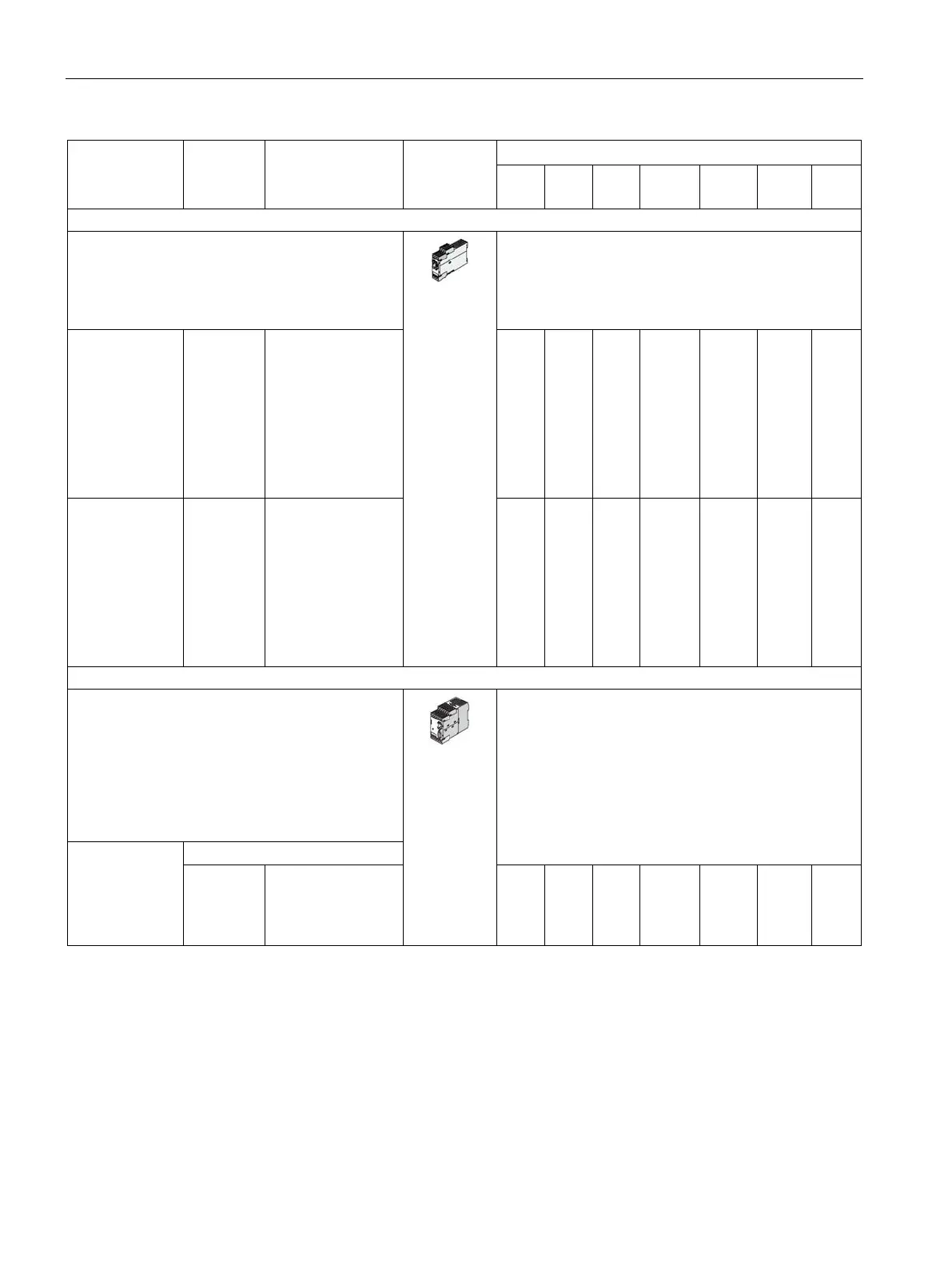
Up to two digital modules can be used to add
additional binary inputs and relay outputs to the
basic unit. The input circuits of the digital modules
are supplied from an external power supply.
4 binary inputs and 2 relay outputs.
Input
voltage 24 V
DC; monostable
relay outputs
Input
voltage 110 V-
240 V AC/DC;
monostable
— 3UF7300-1AB00-0
3UF7300-1AU00-0
—
—
1
1
1
1
2
2
2
2
2
2
2
2
Input voltage
24 V DC;
bistable relay
outputs
Input voltage
110 V-
240 V AC/DC;
bistable relay
outputs
— 3UF7310-1AB00-0
3UF7310-1AU00-0
—
—
—
—
—
—
2
2
2
2
2
2
2
2
Fail-safe digital module (DM-F)
DM-F Local fail-safe digital module
2)
For fail-safe tripping via hardware signal.
2 relay enabling circuits, wired in parallel;
2 relay outputs, common ground, fail-safe tripping.
Inputs for sensor circuit, start signal, cascading
and feedback circuit
Safety function via DIP switch
Rated control supply voltage Us:
24 V DC
110 to
240 V
3UF7320-1AB00-0
3UF7320-1AU00-0
—
—
—
—
—
—
1 (from
*E07*)
1 (from
1
1
1
1
1
1