Diagnostics
8.1 Diagnostics via LED displays
SIMOTION D4x5-2
Commissioning and Hardware Installation Manual, 02/2012
357
8.1.3 LED displays of the Ethernet interface
The Ethernet ports are equipped with LEDs to display Link and Activity.
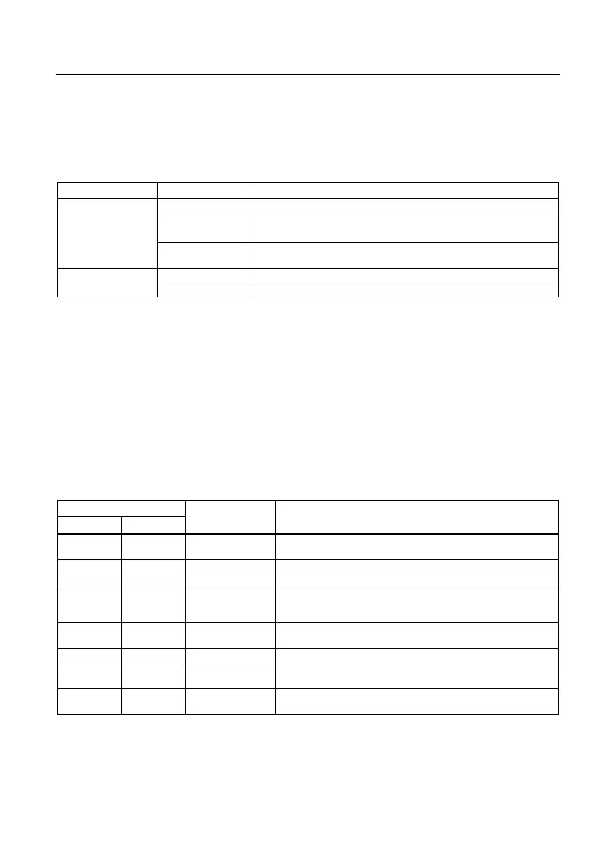
Table 8- 4 State of the Link and Activity LEDs
LED State Meaning
OFF No or faulty connection
Lights up green Transfer rate 10 or 100 Mbit/s:
A different device is connected to port x and a physical connection exists
LINK (upper LED)
Lights up yellow Transfer rate 1,000 Mbit/s:
A different device is connected to port x and a physical connection exists
OFF No data exchange ACT (lower LED)
Flickers yellow Data exchange: Data is being received or sent at port x
8.1.4 LED displays of the CX32-2 controller extension
The different states that occur during power-up are indicated by the LEDs on the CX32-2
controller extension.
● The duration of the individual states varies.
● If an error occurs, the power-up is terminated and the cause is indicated accordingly via
the LEDs.
● At the end of an error-free power-up, all LEDs are switched off briefly.
● After power-up, the LEDs are controlled via the loaded software.
Table 8- 5 Load software
LED
RDY DP
State Comment
Yellow Yellow Reset Hardware reset
All other LEDs light up yellow
Red Red BIOS loaded -
Red 2 Hz Red BIOS error Error occurred while loading the BIOS
Red 2 Hz Red 2 Hz File error
• D4x5-2 CompactFlash card not available or faulty
• Software on D4x5-2 CompactFlash card not available or faulty
Red Yellow
(flashing)
FW loading RDY LED lights up red, DP LED flashes yellow without fixed
frequency
Red Off FW loaded -
Off Red FW checked
(no CRC error)
-
Red 0.5 Hz Red 0.5 Hz FW checked
(CRC error)
CRC invalid
 Loading...


