SIMOTION D4x5-2
Manual, 02/2012
91
Supplementary system components
6
6.1 Connection options overview
Supplementary system components
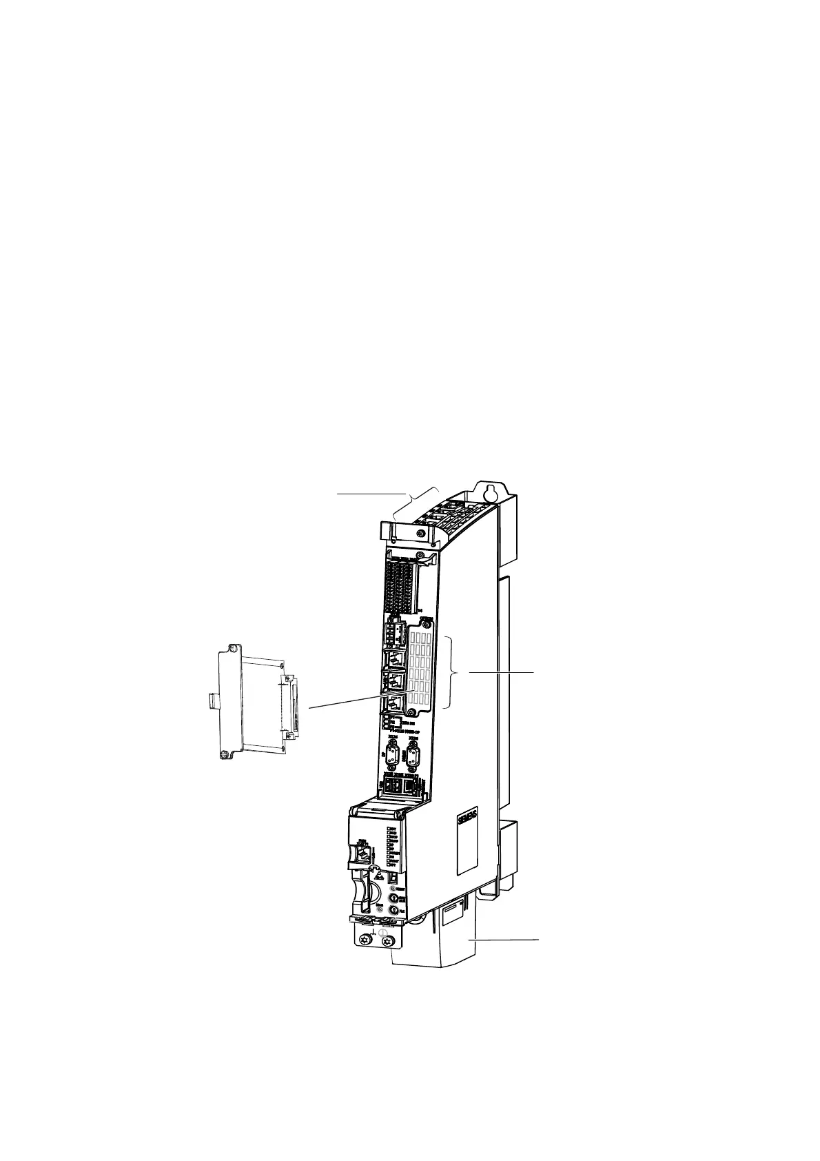
The following figure shows the connection of the supplementary system components. The
connection is:
● Directly on the SIMOTION D module (fan/battery module)
● Via the option slot (TB30, CBE30-2)
● Via the DRIVE-CLiQ interfaces (terminal modules, control unit adapter, ...).
7%RU&%(
RSWLRQDO
'RXEOHIDQ
EDWWHU\PRGXOH
'5,9(&/L4LQWHUIDFHV
IRUWKHFRQQHFWLRQRIV\VWHP
FRPSRQHQWV
2SWLRQVORWZLWKFRYHU
IRUWKHDFFHSWDQFHRI
7%RU&%(
Figure 6-1 Connection of supplementary system components on the D4x5-2