Do you have a question about the Siemens SIMOVERT FC Series and is the answer not in the manual?
The SIMOVERT MASTERDRIVES ATI (Analog Tacho-Interface) is a functional expansion board designed to enable closed-loop speed control using analog tachometers. This board converts the DC voltage generated by an analog tachometer, which is proportional to the speed, into a signal that can be processed by the converter's control board (Control Unit or CU). The ATI supports a wide range of tachometer voltages, typically between 10 V and 300 V, allowing for flexible integration with various analog tachometer types. It is suitable for closed-loop speed control applications within a speed range of 1 RPM to 6000 RPM.
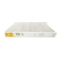
The ATI board (Order No. 6SE7090-0XX84-3DF0) has a rated input voltage of 300 V and a rated output voltage of 0 to ±10 V. It operates within a cooling medium temperature range of 0 °C to +55 °C (32 °F to 131 °F). For storage and transport, the permissible temperature range is -25 °C to +70 °C (-13 °F to 158 °F). The board's dimensions are 90 mm x 83 mm. It is designed for an environmental class of 3K3 for humidity and 3C2 for pollutant exposure, according to DIN IEC 721 Part 3-3 / 04.90. The pollution level is 2 (DIN VDE 0110 Part 1/01.89), and moisture condensation is not permissible. The overvoltage category is II (DIN VDE 0110 Part 2 / 01.89), and the degree of protection is IP20 (DIN VDE 0470 Part1 / 11.92 =^ EN 60529).
In terms of mechanical stability (DIN IEC 68-2-6 / 06.90), during stationary operation, it can withstand a constant amplitude of deflection of 0.35 mm in the frequency range of 10 to 60 Hz, and an acceleration of 49 m/s² (5 g) above 60 to 500 Hz. During transport, it can handle a deflection of 3.5 mm in the frequency range of 5 to 9 Hz, and an acceleration of 9.8 m/s² (1 g) above 9 to 500 Hz.
The ATI is designed for easy installation, snapping onto a mounting rail. For proper operation and to prevent EMC disturbances, screened cables must be used for connections, with the screen connected at one end. Power and control cables should be routed separately. During start-up, it is crucial to ensure that the power supply is switched off and the motor is not rotating, as voltages exceeding 60 V can be present on the board. Adjustment procedures should only be carried out by adequately trained personnel.
The start-up process involves determining the maximum tachometer voltage and the required motor speed. The tachometer is connected to terminals 8-11 of the ATI, and a connection is established between ATI terminals 1-2 and analog input 1 of the control board (CU1/CU2: X102: 30-31; CUVC: X102: 15-16). A continuous shield from the tachometer to the converter is essential, with the shield ground connected to the converter through a large surface area. Parameterization on the basic unit involves setting P208 (S. speed actual value), P210 (an. tach. adjust.), and P652 (set the CU-AE offset to 0). For fine-tuning, the motor can be decoupled from the drive, and the speed can be checked at the operator control panel (monitoring parameter r214 for CU1/CU2 or r218 for CUVC) while adjusting potentiometers R1/R2 for 10 V at maximum speed. Additional smoothing can be achieved with capacitor C2 if required, and solder pins are available for this purpose.
The documentation emphasizes the importance of handling electronic boards with care to prevent damage from electrostatic discharge (ESD). This includes discharging the human body before touching boards, avoiding contact with highly insulating materials, placing boards only on conductive surfaces, and storing/transporting them in conductive packaging. The manual also outlines residual risks associated with Power Drive Systems (PDS), such as undesired movements, extraordinary temperatures, dangerous contact voltages, operational electrical/magnetic/electromagnetic fields, and pollutant emissions. It stresses that only qualified personnel should work on or around the equipment, being thoroughly familiar with all safety and maintenance procedures. Proper transport, storage, installation, and operation are critical for safe and successful functioning. The warranty information clarifies that Siemens AG's sales contract contains the entire obligation, and statements in the documentation do not create new warranties.
| Brand | Siemens |
|---|---|
| Model | SIMOVERT FC Series |
| Category | Industrial Equipment |
| Language | English |