Operating and Programming — Milling Page 34 808D
Create Part
Program
Part 1
s
Basic Theory
Behavior at
corners
Activation/
deactivation of the
tool radius compen-
sation when working
on the part contour.
G41 / G42 and G40
With G41/G42,
the tool radius com-
pensation will be
done in the direction
of travel.
G41:Compensation
to left
G42:Compensation
to right
G40:Compensation
of the radius can be
deactivated
Arrow indicates the
direction of tool motion
along the contour.
G41 → direction
along the tool mo-
tion, tool is always
on the left of the
contour.
G42 → direction
along the tool mo-
tion, tool is always
on the right of the
contour.
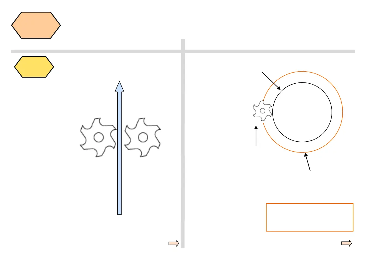
Contour feedrate with
CFC
Direction for com-
pensation, left of
contour will be
G41
Feedrate calcu-
lated when using
tool center, inside
or outside of the
contour
The result of the two commands will
be such that the cutter goes very fast
around a corner or slow on the con-
tour.
When traversing circular
contours with cutter radius
compensation, it should be
decided whether the feed
rate should be calculated
along the contour of the
workpiece or along the path
defined by the center point
of the cutting tool.
When using a contour with
a feed rate defined by the
CFC code, the feed rate will
be constant at the contour,
but in some cases, it may
cause increases in the feed
rate of the tool.
This increase could dam-
age the tool if excessive
material is encountered at
the contour; this function is
normal for finish cutting of
contours.
The CFTCP command
ensures a constant feed
rate, however a constant
feed rate may not be en-
sured at the contour, which
may cause deviations in
surface finish.
 Loading...


