808D Page 79 Operating and Programming — Milling
Additional
Information
Part 2
s
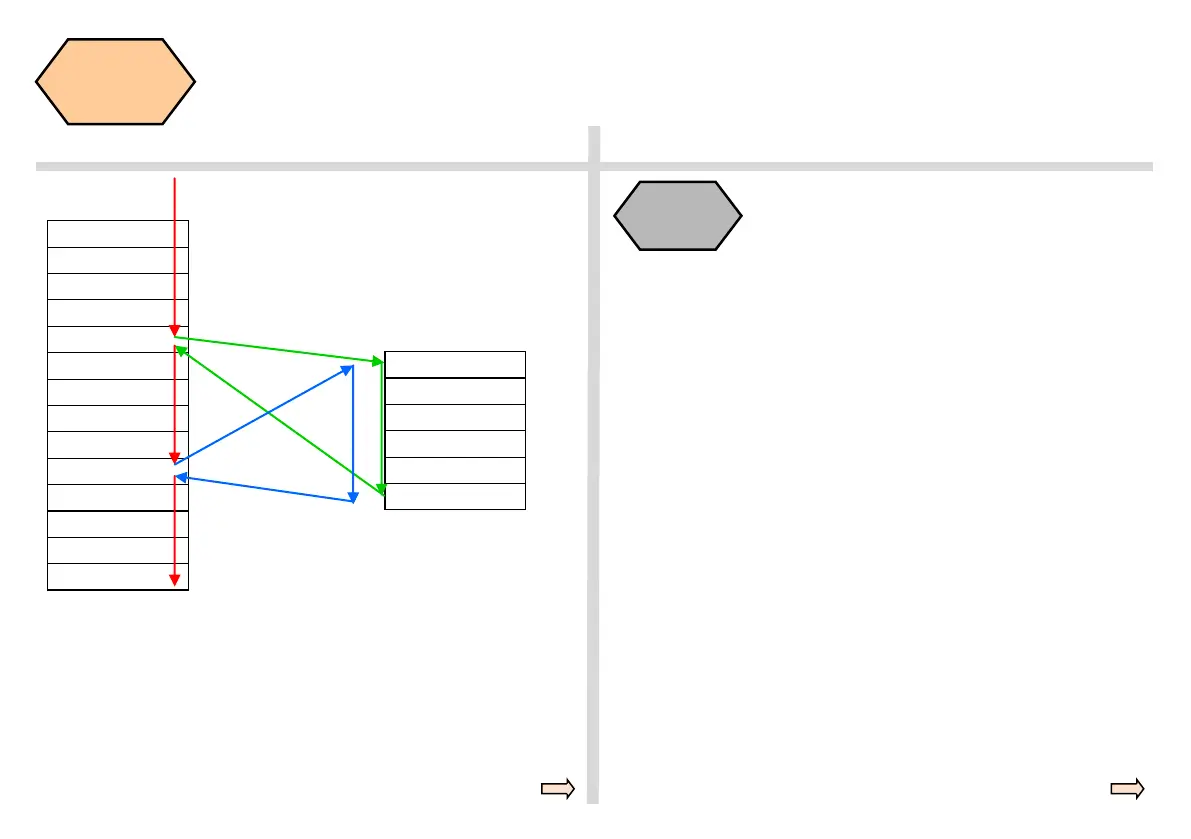
SEQUENCE
Main program
MAIN 123
...
...
...
N20 L10; call
...
...
...
...
N80 L10; call
...
...
...
M30
Subprogram
L10
N10 R1=34…
N20 X...Z….
…
...
M17
Sequence
Subprograms can be called from a main program, and also from another
subprogram. In total, up to eight program levels, including the main pro-
gram, are available for this type of nested call.
In addition to the common specification in Cartesian coordinates (X, Y,
Z), the points of a workpiece can also be specified using polar coordi-
nates.
Polar coordinates are also helpful if a workpiece or a part of it is dimen-
sioned from a central point (pole) with specification of the radius and the
angle.
The polar coordinates refer to the plane activated with G17 to G19. In
addition, the third axis perpendicular to this plane can be specified. When
doing so, spatial specifications can be programmed as cylindrical coordi-
nates.
The polar radius RP= specifies the distance of the point to the pole. It is
saved and must only be written in blocks in which it changes, after the
pole or the plane has been changed.
The polar angle AP= is always referred to the horizontal axis (abscissa)
of the plane (for example, with G17: X axis). Positive or negative angle
specifications are possible. The positive angle is defined as follows:
Starting from the plus direction of X axis and rotates CCW.
It is saved and must only be written in blocks in which it changes, after
the pole or the plane has been changed.
Polar
coordinates
 Loading...


