Operating and Programming — Milling Page 80 808D
Additional
Information
Part 2
s
Basic Theory
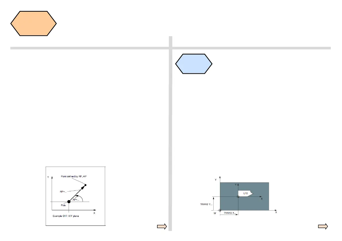
The programmable workpiece offsets TRANS and ATRANS can be used
in the following cases:
● For recurring shapes/arrangements in various positions on the work-
piece
● When selecting a new reference point for dimensioning
This results in the current workpiece coordinate system.
TRANS X...Y... Z... ; programmable offset(absolute)
ATRANS X...Y... Z... ; programmable offset, additive to existing offset
(incremental)
TRANS ; without values, clears old commands for offset
Programming example
N20 TRANS X20.0 Y15.0 programmable offset
L10 subprogram call
G110 Pole specification relative to the setpoint position last programmed
(in the plane, e.g. with G17: X/Y)
(when using G110, please always take the current position of the
tool as the reference point to specify the new pole)
G111 Pole specification relative to the origin of the current workpiece
coordinate system (in the plane, e.g. with G17: X/Y)
G112 Pole specification, relative to the last valid pole; retain plane
Programming example
N10 G17 ; X/Y plane
N20 G111 X17 Y36 ; pole coordinates in the current workpiece
AP=45 RP=50 coordinate system
...
N80 G112 X35.35 Y35.35 ; new pole, relative to the last pole as a
AP=45 RP=27.8 polar coordinate
N90 ... AP=12.5 RP=47.679 ; polar coordinate
N100 ... AP=26.3 RP=7.344 Z4 ; polar coordinate and Z axis(= cylinder
coordinate)
Additive
workpiece
offsets
 Loading...


