B520
B520 Page 24 840D/828D SINUMERIK Operate
Notes
Section 6
Measuring a tool
6.5 Calibrate the tool probe
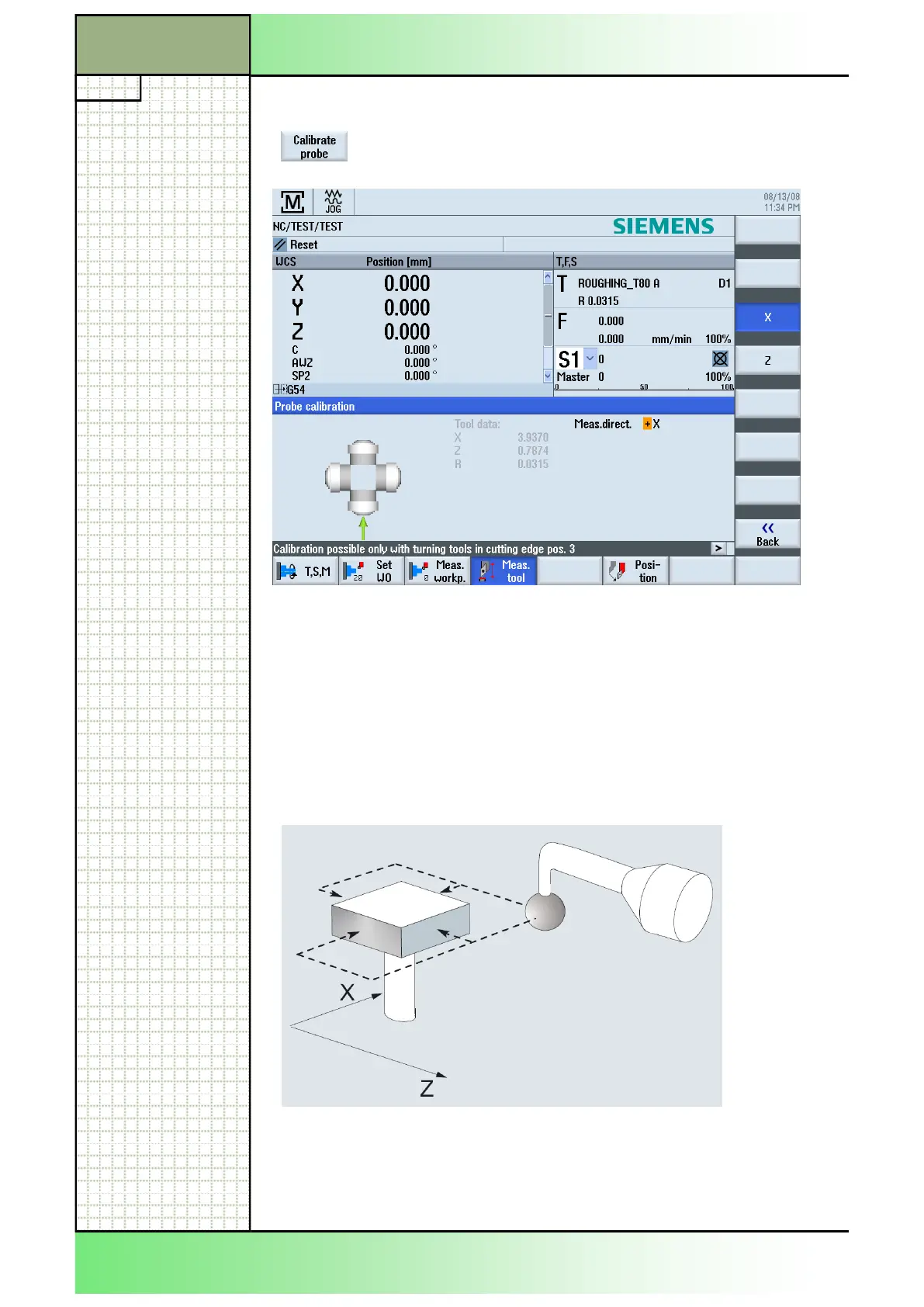
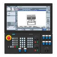
By pressing the VSK 6 "Calibrate probe" the "Probe
calibration" input mask is displayed on the screen.
To be able to measure the tools automatically, the position of the tool
probe in the machine area in relation to the machine zero must be deter-
mined first.
The probe must be approached from four directions (+X, -X, +Z, -Z) for
calibration purposes.
To do this, a calibrating tool must be used, which you can use to approach
the tool probe in all the required directions.
The calibrating tool must be a turning tool type (roughing or finishing tool).
Cutting edge positions 1 - 4 can be used for the tool probe calibration.
You must enter the length and the radius or diameter of the calibrating tool
in the tool list.
Note:
If a second probe is installed on the counterspindle, the machine manufac-
turer must have been set up in a machine datum in a machine datum.
Refer to the machine manufacturer„s specifications.





 To Next Page