Connecting
7.6 Use of Ethernet interfaces
NCU 7x0.2
56 Manual, 02/2011, 6FC5397-0AP20-0BA0
LED displays
For diagnostic purposes, the RJ45 sockets are each equipped with a green and an orange
LED. This allows the following status information about the respective Ethernet port to be
displayed:
Table 7- 10 Ethernet port LED displays
LED Status Meaning
On 10 or 100 Mbit link available Green
Off Missing or faulty link
On Receive or transmit activity Orange
Off No activity
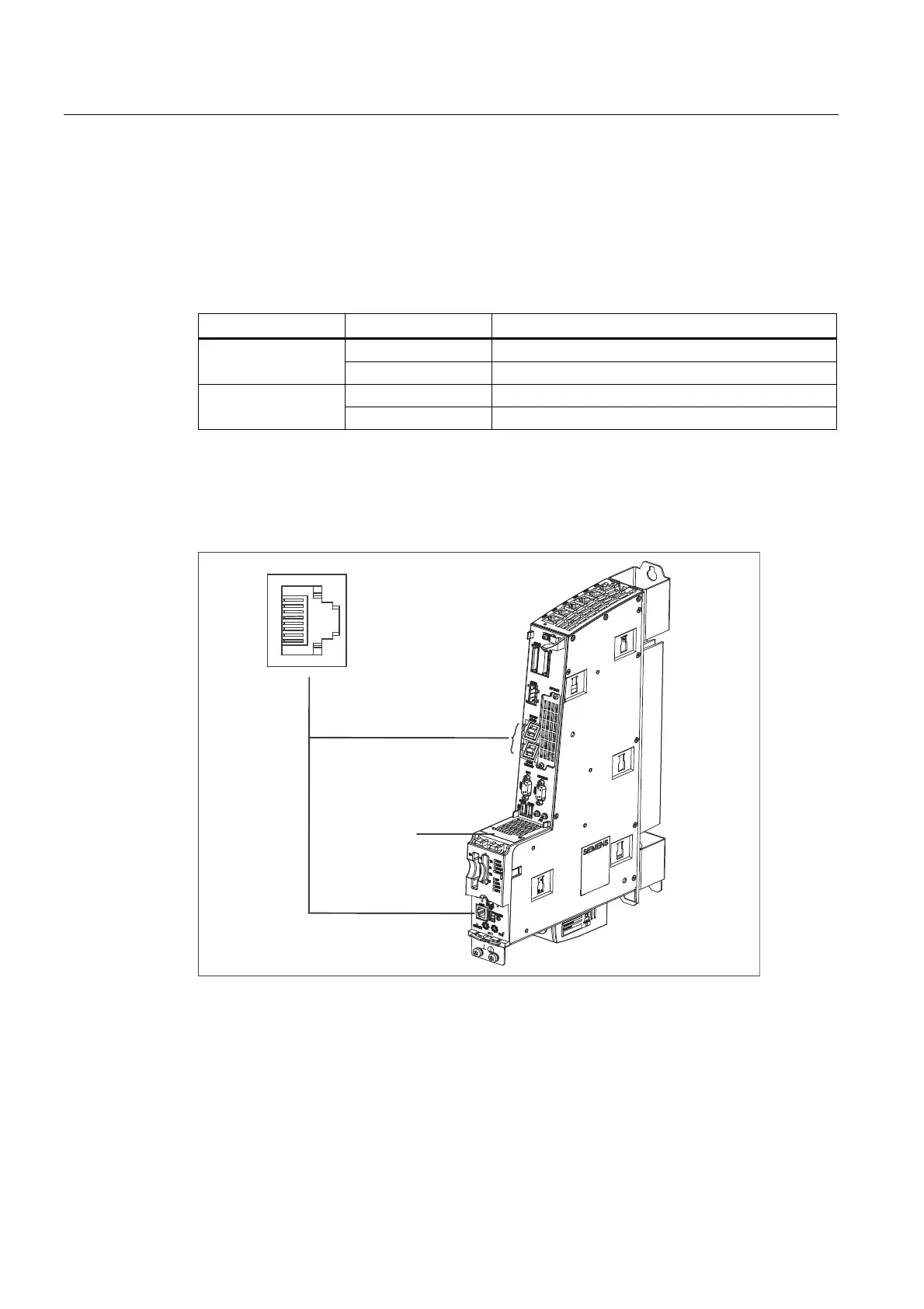
Position of connectors
The following figure shows the mounting position and designation of the Ethernet connectors
on the module.
$GKHVLYHODEHOZLWK
0$&DGGUHVVHV
;
;;
Figure 7-5 Position of the Ethernet interfaces
 Loading...


