Connecting
7.7 PROFINET
NCU 7x0.2
Manual, 02/2011, 6FC5397-0AP20-0BA0
59
NOTICE
CNC software V2.6 with PLC software V2.7
Ports 1 and 2 are freely available for use, but ports 3 and 4 are deactivated. With PLC
software < V2.7, the full range of options for PROFINET-based communication can only be
guaranteed for port 1.
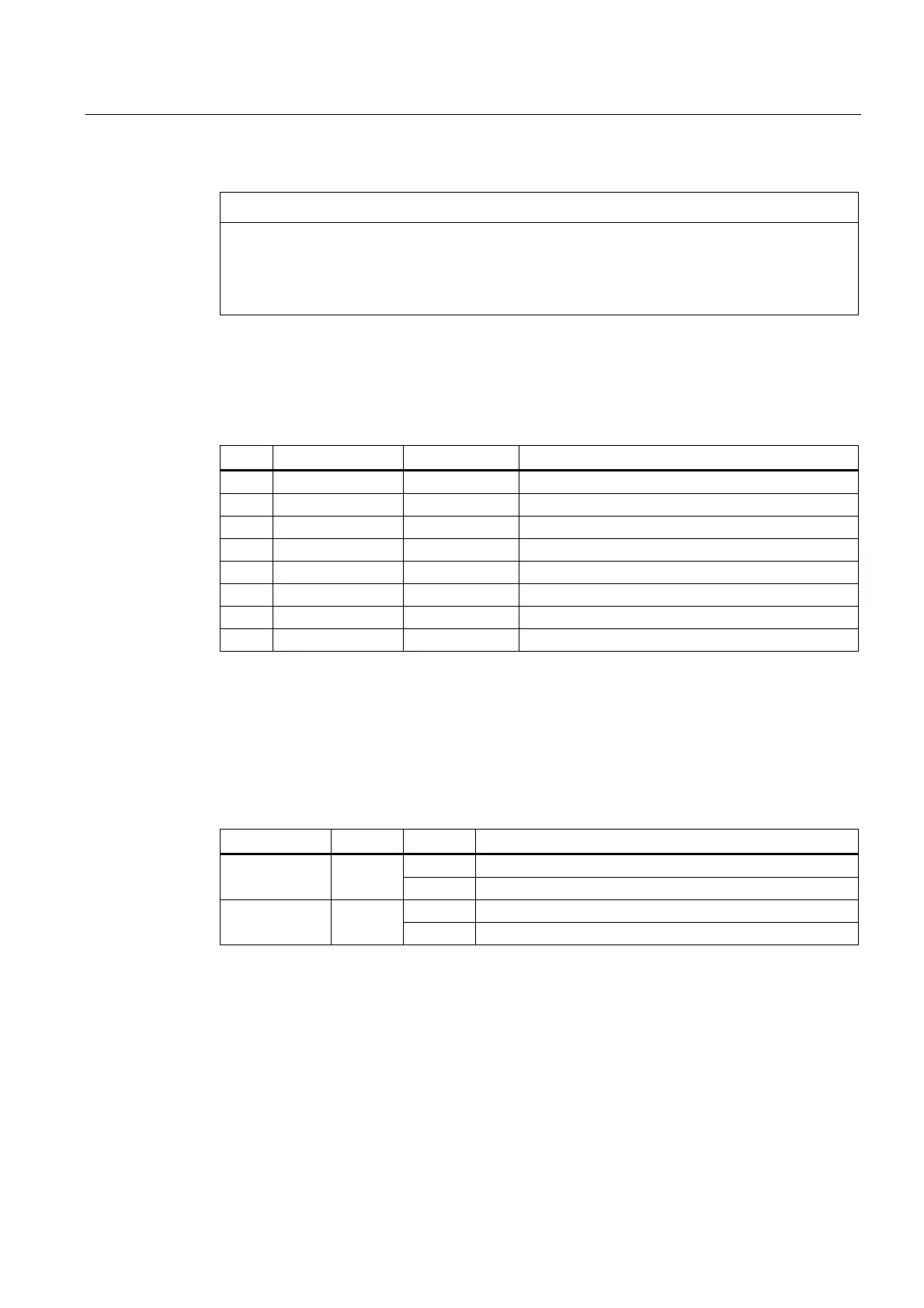
Pin assignment
Table 7- 12 PROFINET interface, ports 1, 2
Pin Signal name Signal type Meaning
1 TX+ Output Transmit data +
2 TX- Output Transmit data -
3 RX+ Input Receive data +
4 NC
5 NC
6 RX- Input Receive data -
7 NC
8 NC
LED displays
For diagnostic purposes, the RJ45 sockets are each equipped with a green and an orange
LED. This allows the following status information about the respective PROFINET port to be
displayed:
Table 7- 13 PROFINET ports LED displays
Name Color Status Meaning
On 100 MBit link available Link Green
Off Missing or faulty link
On Sending or receiving Activity Orange
Off No activity
Beneath the ports are two LEDs with no specific function.
 Loading...


