Connecting
7.8 PROFIBUS / MPI
NCU 7x0.2
66 Manual, 02/2011, 6FC5397-0AP20-0BA0
Pin assignment for X126, X136
Table 7- 17 PROFIBUS DP interfaces (X126, X136)
Pin Signal name Signal type Meaning
1 - - Reserved, do not use
2 G VO Ground to P24_SERV
3 2RS_DP B RS-485 differential signal
4 2RTS_DP O Request to send
5 1G VO Ground to 1P5
6 1P5 VO 5 V power supply for bus terminal, external, short-circuit proof
7 P24_SERV VO 24 V for teleservice, short-circuit proof, 150mA maximum
8 2XRS_DP B RS-485 differential signal
9 - - Reserved, do not use
The 1P5 voltage is provided exclusively to supply the bus terminal.
Signal type: VO = Voltage output (power supply) O = Output; B = Bidirectional
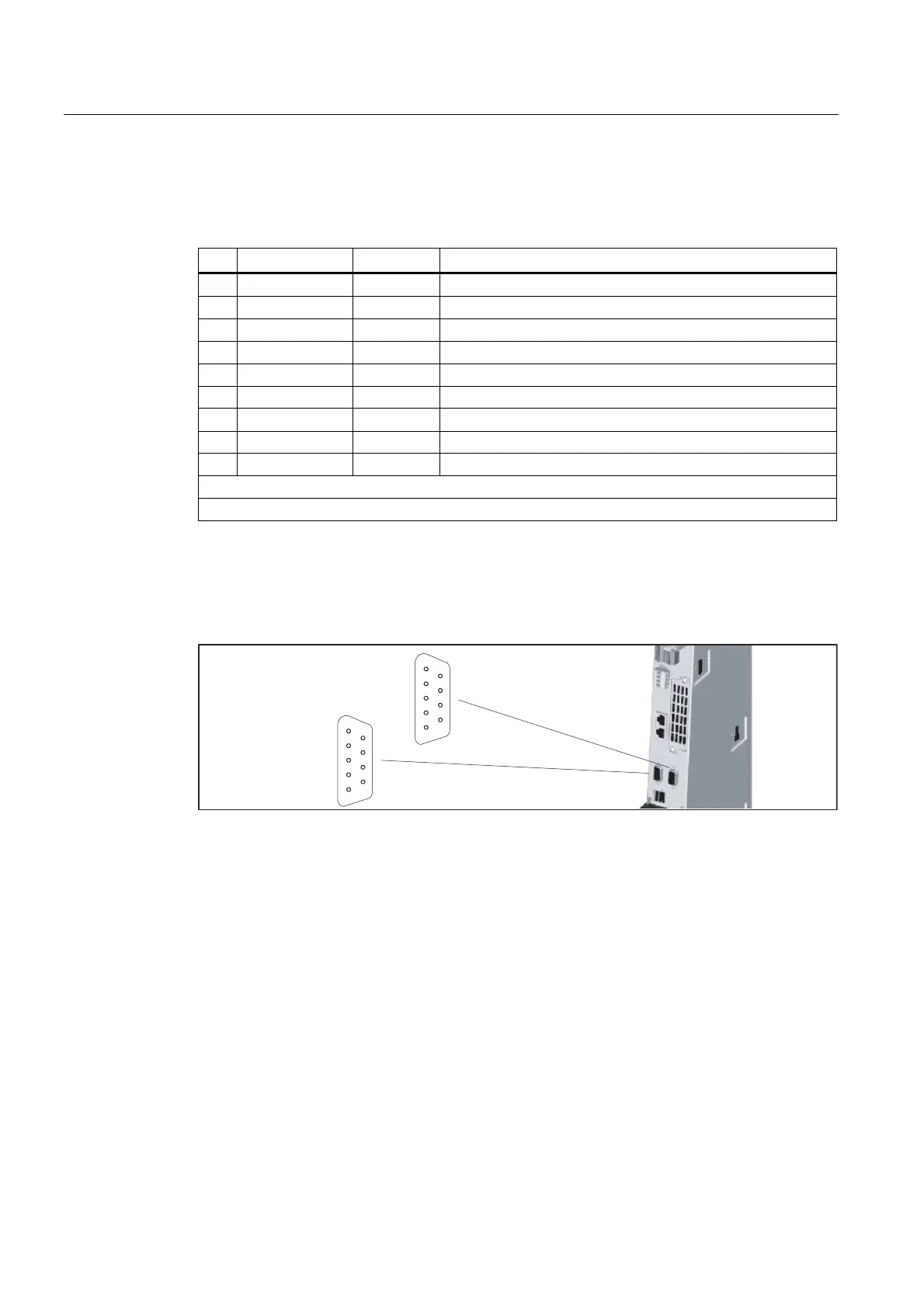
Position of connectors
The following figure shows the mounting position and designation of the connectors on the
Control Unit.
;
'3
'303,
;
Figure 7-11 PROFIBUS DP/MPI interfaces
 Loading...


