Connecting
7.9 Digital inputs/outputs
NCU 7x0.2
72 Manual, 02/2011, 6FC5397-0AP20-0BA0
The enables for the drive units and/or motors (Line Module, Motor Module) connected to the
control unit can be switched using the digital inputs.
Note
Terminal assignments
When commissioning the drive wizard, the digital inputs/outputs are correspondingly
preassigned functions.
For more information about terminal assignment, see:
System Manual "Machine Configuration Guidelines", Chapter "Commmunications in the
System", 10/2009 Edition.
Commissioning Manual "IBN CNC: NCK, PLC, Drive", Chapter "Tips", 03/2010 Edition.
Access to digital inputs/outputs
Note
The digital inputs/outputs are updated in accordance with the set PROFIBUS bus clock pulse
for SINAMICS Integrated.
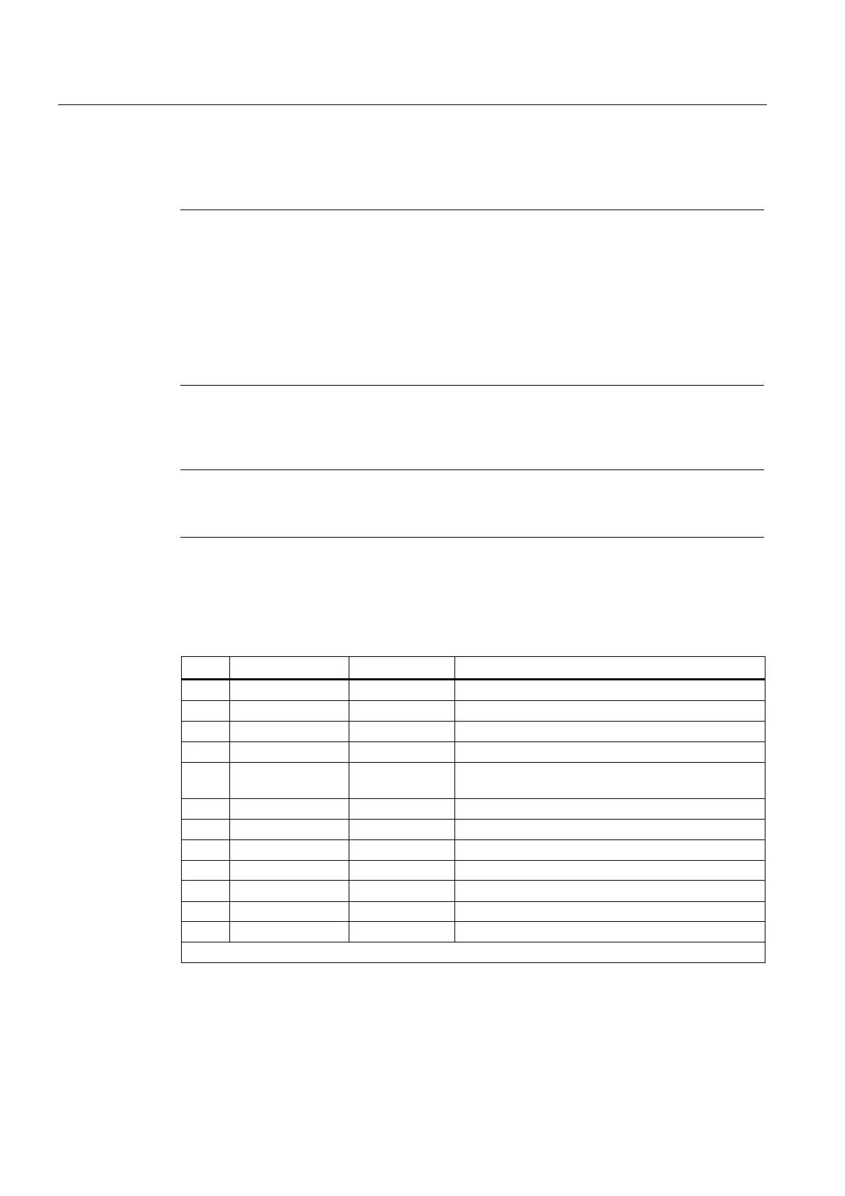
Pin assignment
Table 7- 22 X122 digital inputs/outputs
Pin Signal name Signal type Meaning
1 DI0 I Digital input 0
2 DI1 I Digital input 1
3 DI2 I Digital input 2
4 DI3 I Digital input 3
5 G1 GND Ground for DI0 - DI3 (functionally-separated relative
to G)
6 G GND Ground
7 DI/DO8 B Digital input/output 8
8 DI/DO9 B Digital input/output 9 (rapid input)
9 G GND Ground
10 DI/DO10 B Digital input/output 10 (rapid input)
11 DI/DO11 B Digital input/output 11 (rapid input)
12 G GND Ground
Signal type: B = Bidirectional; I = Input; GND = Reference potential (ground)
 Loading...


