Connecting
7.9 Digital inputs/outputs
NCU 7x0.2
Manual, 02/2011, 6FC5397-0AP20-0BA0
77
Digital inputs/outputs on X122/X132
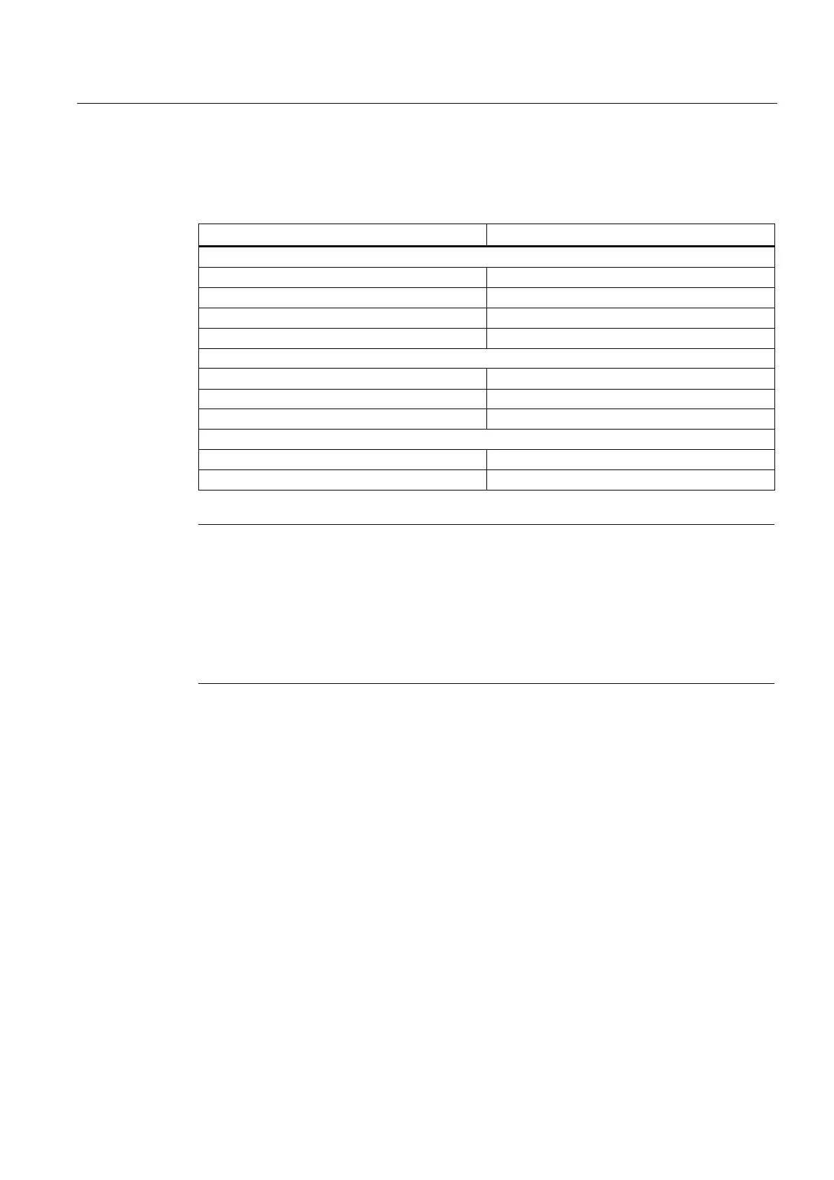
Table 7- 26 Technical data of the digital inputs/outputs of X122/X132
Parameters Values
As an input
Voltage -3 V to 30 V
Typical power consumption 10 mA at 24 V DC
Signal level (including ripple) High signal level: 15 V to 30 V
Low signal level: -3 V to 5 V
Pins 8, 10 and 11 are "rapid inputs"
Signal propagation delays of inputs/"rapid inputs" L → H: 50 μs/5 μs
H → L: 100 μs/50 μs
As an output
Voltage 24 V DC
Maximum load current per output 500 mA
Note
An open input is interpreted as "low".
Only "rapid inputs" can be used as inputs for BEROs and probes.
Terminals G1 or G2 must be connected for the digital inputs to work. This can be done as
follows:
Connect the coupled-motion ground reference of the digital inputs, or provide a jumper to
terminal G. (Notice! This removes the galvanic isolation for these digital inputs.)
 Loading...


