The provided document is an equipment manual for the SINUMERIK ONE MCP Part 2: MCP 2400, a machine control panel manufactured by Siemens. This manual is part of a two-part documentation set, with Part 1 covering general information applicable to all SINUMERIK ONE MCPs, and Part 2 detailing the specifics of the MCP 2400. The manual is dated 08/2023 and has the article number A5E50324707B AB.
Function Description
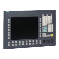
The SINUMERIK ONE MCP 2400 is a machine control panel designed for industrial use, particularly with machine tools and production machines. It serves as an interface for operators to control and monitor the SINUMERIK ONE control system, as well as SINUMERIK 840D sl/840DE sl systems. The panel integrates various input and display elements to facilitate machine operation.
Key functional areas visible on the front side of the MCP 2400 include:
- Emergency Stop Button: A prominent red button for immediate machine shutdown in critical situations, indicating a crucial safety function.
- QWERTY Keyboard: A full alphanumeric keyboard for data entry, programming, and command input.
- Mounting Space for Elements: Dedicated spaces (6x for 22.5 mm elements and 4x for 22.5 mm elements) allow for the integration of additional machine-specific controls or indicators, offering customization.
- Key-operated Authorization Switch: A security feature to control access and operational privileges, ensuring only authorized personnel can operate certain functions.
- Powerride Controls (Feed and Spindle): Two "Powerride" units (Powerride 1 for feed and Powerride 2 for spindle) likely provide proportional or continuous control over machine axes and spindle speed, complemented by associated keypads (keypad 4.1 and keypad 4.2).
- Keypads: Multiple keypads are present, including Keypad 4 (axis block), Keypad 3 (customer keys), Keypad 2 (customer keys), and Keypad 1 (operating mode block). These keypads offer dedicated buttons for specific machine functions, customer-defined operations, and selection of operating modes. The "customer keys" indicate flexibility for machine builders to assign custom functions.
The rear side of the MCP 2400 reveals its connectivity options, which are essential for its integration into a machine control system:
- Protective Conductor Connection: Ensures proper grounding for electrical safety.
- Power Supply Interface X10: The main connection for electrical power.
- Switch S2: A physical switch for system control.
- Ethernet Interfaces X20 (port 1/port 2): For network communication, enabling data exchange with the control system and other network components.
- Handwheel Connections X60/X61: Dedicated ports for connecting external handwheels, which are often used for precise manual positioning of machine axes.
- Emergency Stop Connection: An interface for the emergency stop circuit.
- Mounting Space for Elements: Similar to the front, additional mounting spaces (4x for 22.5 mm elements) are available on the rear for further customization or integration of components.
- Interface for Customer-Specific Inputs/Outputs X516 and X515: These interfaces provide flexibility for connecting various customer-specific sensors, actuators, or other I/O devices, allowing for tailored machine integration.
The configuration section outlines how the various input and output elements are mapped to specific slots, indicating a modular design. For example, Slot 1 is typically the Base, Slot 2 for Keypad 1 (operating mode block), Slot 3 for Keypad 2 (customer keys), and so on, up to Slot 9 for Handwheel 2. This modularity allows for flexible assembly and replacement of components.
Important Technical Specifications
The MCP 2400 adheres to various safety and environmental standards, ensuring robust and reliable operation in industrial settings.
Safety:
- Safety class: III; PELV (Protective Extra Low Voltage) according to EN 50178.
- Degree of protection: Front: IP65 (dust-tight and protected against water jets); Keyswitch: IP54 (protected against dust and splashing water); Rear: IP00 (no protection against ingress of solid objects or water).
- Approvals: CE / UL / EAC.
- Flame resistance: UL 94 V-1.
- UL identifier: MCPS2003-585265E-1282111AA0.
Electrical Data:
- Overvoltage category: Secondary circuit supplied from primary circuits up to Cat. III (OVC III), 300 V AC.
- Power supply: 24 V DC (range: 20.4 V ... 28.8 V). It is crucial to connect the device only to a 24 V DC power supply compliant with PELV requirements.
- Power consumption (max. at 28.8 V):
-
-
-
- 24 V load on X515/X516: 16x 0.15 A
- Total: 115 W
- Current consumption (max. at 20.4 V): 4.7 A.
Mechanical Data:
- Dimensions (W x H x D): 585 x 265 x 55 mm (without handwheel).
- Weight: 3.4 kg.
- Permissible vertical mounting positions: 0° - 90°.
- Tightening torques (max.): M3: 0.5 Nm; M4: 1 Nm; M5: 1.5 Nm. Grounding: 3 Nm, hold bottom nut in place.
- Installation clearance: 55 mm.
- Panel cutout: 562 x 242 mm, with 16 M5 nuts for securing, tightened to 1.5 Nm. Spring elements should be used in addition to the M5 nuts.
Climatic Environmental Conditions:
- Classification: 3K3 according to EN 60721-3-3.
- Heat dissipation: By natural convection.
- Condensation and ice formation: Not permitted.
- Supply air: Without corrosive gases, dusts and oils.
- Max. installation altitude: Up to 1000 m without derating. From 1000 m to 4000 m, linear ambient temperature derating of -0.5 K per 100 m applies.
- Temperature limit values (storage): -40 ... 70 °C (cyclic).
- Temperature limit values (operation): 0 ... 45 °C (front), 0 ... 55 °C (rear).
- Temperature change: Max. 30 K/h.
- Relative humidity: 5 ... 90% (without condensation).
- Permissible change in relative humidity: Max. 6%/h.
- Pollution degree: 2 (only use indoors).
Mechanical Environmental Conditions:
- Vibration load during operation: Frequency range: 10-200 Hz; Deflection at 9-18 Hz: 1.5 mm; Acceleration at 18-200 Hz: 2 g.
- Shock load during operation with shock-sensitive components: Acceleration: 5 g, Shock duration: 30 ms.
- Shock load during operation without shock-sensitive components: Acceleration: 15 g, Shock duration: 11 ms.
- Load: 3x in each direction.
EMC:
- EMC conducted / radiation: Class C2 according to EN 61800-3. In a residential environment, this product may cause high-frequency interference, requiring suppression measures.
Emergency Stop Button:
- Rated voltage: 24 V DC.
- Current rating (max.): 3 A.
- Current rating (min.): 1 mA.
- Switching capacity: DC 13 according to EN 60947-5-1.
- Conditional rated short-circuit current: 10 A gL/gG according to EN 60947-5-1.
- B10d value: 500,000.
Usage Features
The SINUMERIK ONE MCP 2400 is designed for intuitive and flexible operation in industrial environments.
- Customizable Key Labeling: The keys feature replaceable caps that can be freely inscribed using a laser for machine-specific adaptations. Alternatively, transparent key caps with insert labels can be used, allowing for clear and adaptable function assignments.
- Modular Design: The presence of multiple keypads (operating mode block, customer keys, axis block) and mounting spaces for additional elements highlights a modular approach, enabling machine builders to tailor the control panel to specific machine requirements.
- Integrated Safety: The prominent emergency stop button and key-operated authorization switch are critical safety features, ensuring safe operation and controlled access.
- Ergonomic Controls: The inclusion of Powerride units and handwheel connections suggests a design that supports both automated and manual, precise control of machine movements.
- Robustness: The IP65 protection rating for the front panel indicates resistance to dust and water jets, making it suitable for harsh industrial environments.
- Connectivity: Multiple Ethernet ports and customer-specific I/O interfaces provide extensive connectivity options for integration into complex machine systems and networks.
Maintenance Features
The manual provides several important notes regarding the proper use and maintenance of the MCP 2400 to ensure its longevity and safe operation.
- Qualified Personnel: Operation and maintenance should only be performed by personnel qualified for the specific task, adhering to warning notices and safety instructions.
- Proper Use: Siemens products must only be used for applications described in the catalog and technical documentation. Any third-party components must be recommended or approved by Siemens.
- Environmental Conditions: Compliance with permissible ambient conditions (temperature, humidity, pollution degree) is crucial to prevent damage.
- ESD Protection: Electronic components are sensitive to electrostatic discharge. Proper handling procedures, such as wearing an ESD wrist strap and using conductive surfaces, are required during installation and maintenance to prevent damage.
- Tightening Tools: Only suitable tightening tools and specified torques should be used for screws to prevent damage to the equipment. Regular adjustment of tools is recommended.
- Ventilation: Adequate ventilation clearances must be maintained to prevent overheating, which can lead to fire and reduced service life.
- Cybersecurity: Keeping software up to date, incorporating automation and drive components into an industrial cybersecurity concept, and protecting stored files from malicious software are essential for preventing unsafe operating states due to software manipulation.
- Coolants and Lubricants: While designed for industrial use, contact between operator components and aggressive coolants and lubricants should be avoided, as resistance to all such substances cannot be guaranteed.
- Grounding: The device must be grounded in compliance with applicable regulations to prevent electric shock.
- Cable Shields: Cable shields must be connected at one end to the grounded housing potential to prevent hazardous touch voltages from capacitive cross-coupling.
- Radio Devices: Radio devices, cellphones, or mobile WLAN devices should be switched off if moved closer than 20 cm to the components to prevent malfunctions that could impair functional safety.
- Power Supply: The 24 V DC power source must be adapted to the input data of the device and comply with PELV requirements.
- Fire Protection: Built-in devices should be installed in robust metal control cabinets, and operated with doors closed, ensuring smoke can only escape via controlled paths.