Pin Signal name Type Pin Signal name Type
39 Output 5.0 O 40 Output 5.1 O
41 Output 5.2 O 42 Output 5.3 O
43 Output 5.4 O 44 Output 5.5 O
45 Output 5.6 O 46 Output 5.7 O
47 DOCOM3 VI 48 DOCOM3 VI
49 DOCOM3 VI 50 DOCOM3 VI
VI: Voltage input / VO: Voltage output
I: Signal input / O: Signal output / GND: Reference potential (ground)
Digital inputs
Characteristics
• X222: Inputs 3.0 to 3.7 are connected as rapid inputs; this means the input lter has a max.
delay time of 600 μs.
• The inputs have no signaling (status LEDs).
• The inputs are not isolated.
• It is not possible to connect 2-wire BEROs.
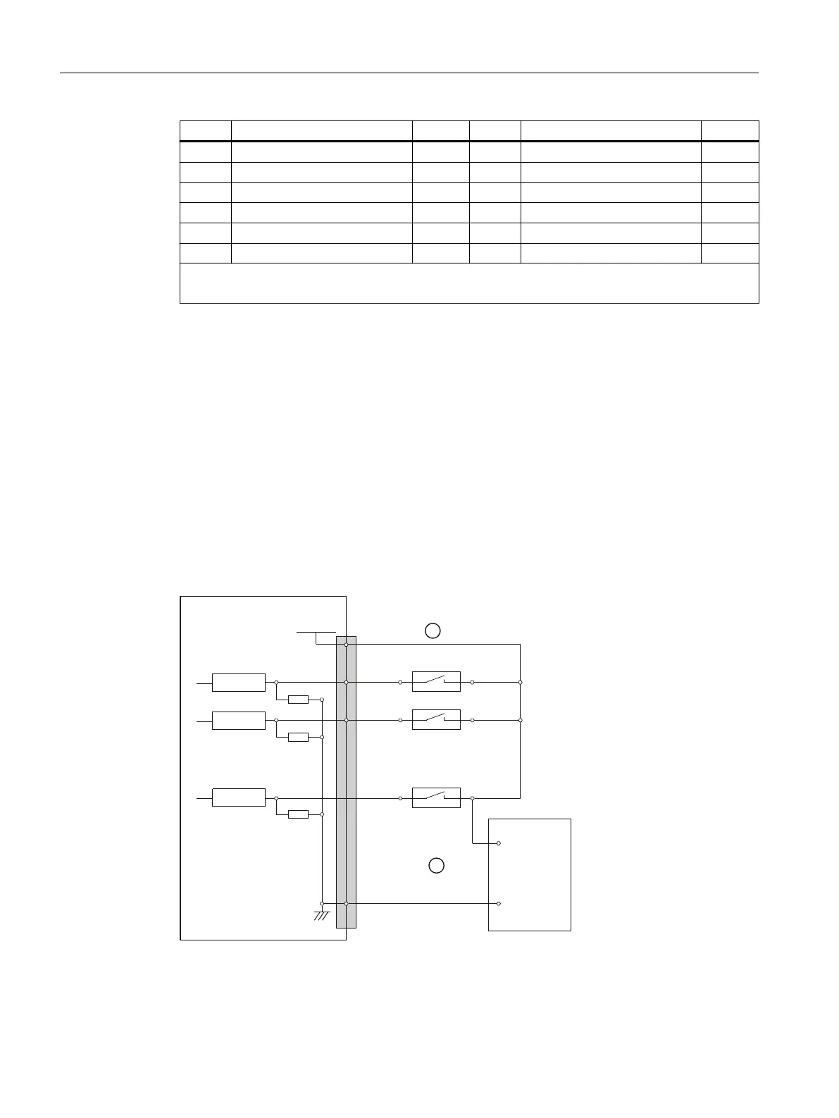
Terminal assignment for the digital inputs
The following gure shows an example of the terminal assignment for the digital inputs on
connector X111. Connectors X222 and X333 are assigned analogously.
3LQQXPEHU
5HFHLYHU
([WSRZHUVXSSO\
3287H[W
VWDELOL]HG
5HFHLYHU
5HFHLYHU
33'31
;;;
3287
9'&
0
9
9
① when using the internal power supply P24OUT
② when using an external power supply P24OUT
ext
Connectable components
12.2 PP 72/48D PN
NCU 1750
124 Equipment Manual, 01/2022, A5E45627807B AE
 Loading...


