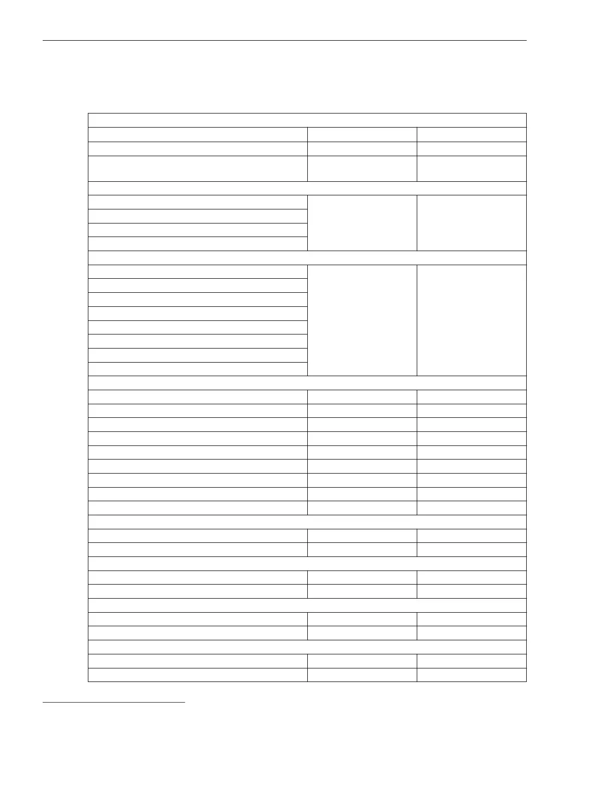
Voltage Controller
Setting Values
General Information
I reference for % values
91
1.0 A to 100 000.00 A Increments of 0.1 A
V reference for % values
92
0.200 kV to 1 200.000 kV Increments of 0.001 kV
Rated app. power transf.
93
0.20 MVA to 5000.00
MVA
Increments of 0.01 MVA
Volt. cont. 2W
Target voltage 1
110.000 V to 340.000 kV Increments of 0.001 kV
Target voltage 2
Target voltage 3
Target voltage 4
Volt. cont. 3W and GC
Target voltage 1 w1
110.000 V to 340.000 kV Increments of 0.001 kV
Target voltage 2 w1
Target voltage 3 w1
Target voltage 4 w1
Target voltage 1 w2
Target voltage 2 w2
Target voltage 3 w2
Target voltage 4 w2
Volt. cont. 2W, 3W, and GC
Bandwidth 0.2% to 10.0% Increments of 0.1%
T1 delay 5 s to 600 s Increments of 1 s
T1 Inverse Min 5 s to 100 s Increments of 1 s
T2 delay 0 s to 100 s Increments of 1 s
Fast step down limit 0.0 % to 50.0 % Increments of 0.1 %
Fast step down T delay 0.0 s to 10.0 s Increments of 0.1 s
Fast step up limit -50.0 % to 0.0 % Increments of 0.1 %
Fast step up T delay 0.0 s to 10.0 s Increments of 0.1 s
Function monitoring 1 min to 120 min Increments of 1 min
Line compensation LDC-Z
Target voltage rising 0.0% to 20.0% Increments of 0.1%
Max load current 0.0% to 500.0% Increments of 0.1%
Line compensation LDC-XandR (two-winding transformer)
R line 0.00 Ω to 30.00 Ω Increments of 0.01 Ω
X line -30.00 Ω to 30.00 Ω Increments of 0.01 Ω
Line compensation LDC-XandR
R line 0.0 Ω to 30.0 Ω Increments of 0.1 Ω
X line -30.00Ω to 30.0 Ω Increments of 0.1 Ω
Limiting values
Vmin threshold 10.000 kV to 340.000 kV Increments of 0.001 kV
Vmin time delay 0 s to 20 s Increments of 1 s
11.37
91
Only visible in the voltage-control operation without parallel operation
92
Only visible in the voltage-control operation without parallel operation
93
Only visible in the voltage-control operation without parallel operation
Technical Data
11.37 Voltage Controller
1202 SIPROTEC 5, High-Voltage Bay Controller, Manual
C53000-G5040-C015-A, Edition 05.2018

 Loading...


