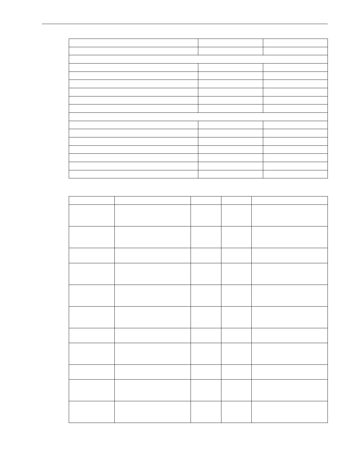
Vmax threshold 10.000 kV to 340.000 kV Increments of 0.001 kV
Vmax time delay 0 s to 20 s Increments of 1 s
Blockings
V< Threshold 10.000 kV to 340.000 kV Increments of 0.001 kV
V< Time delay 0 s to 20 s Increments of 1 s
I> Threshold 10 % to 500 % Increments of 1 %
I> Time delay 0 s to 20 s Increments of 1 s
I< Threshold 3 % to 100 % Increments of 1 %
I< Time delay 0 s to 20 s Increments of 1 s
Parallel control
Parallel-transfomer id 0 to 8 Increments of 1
Maximal tap difference 1 to 9 Increments of 1
Reactive I control factor 0.01 to 100.00 Increments of 0.01
VT supervision threshold 0.5% to 10.0% Increments of 0.1 %
VT supervision time delay 1 s to 600 s Increments of 1 s
Circul. current threshold 10 % to 500 % Increments of 1 %
Circul. current time delay 0 s to 1000 s Increments of 1 s
Measured Values, Two-Winding Transformer
Measured Value Description Primary Secondary % Referenced to
V act.
Current, measured positive-
sequence voltage (referenced
to phase-to-phase)
kV V Target voltage of the primary
system referenced to the rated
voltage
ΔV act.
Voltage difference between
the target voltage and the
actual voltage
% % Voltage difference referenced
to the rated voltage of the
controlled winding
I load
Current measured load current
(positive-sequence system)
A A Load current referenced to the
rated value of the function
V max
Maximum positive-sequence
voltage ever measured (refer-
enced to phase-to-phase)
kV V Maximum voltage of the
winding referenced to the
rated voltage of the winding
V min
Minimum positive-sequence
voltage ever measured (refer-
ence to phase-to-phase)
kV V Minimum voltage of the
winding referenced to the
rated voltage of the winding
V target
Calculated target voltage with
consideration of Z compensa-
tion
kV V Target voltage of the winding
referenced to the rated voltage
of the winding
PhAng
Phase angle of the currently
measured load current
° ° -
I load Σ
Sum of the currently measured
load currents. Active when line
compensation is activated.
A A Load current referenced to the
rated current of the function
I circul.
Currently measured circulating
reactive current
A A Circulating reactive current
Vact.m
Currently measured control
voltage
kV V Current voltage of the control
referenced to the rated voltage
of the function
ΔVactV
Voltage difference % % Voltage difference referenced
to the rated voltage of the
function
Technical Data
11.37 Voltage Controller
SIPROTEC 5, High-Voltage Bay Controller, Manual 1203
C53000-G5040-C015-A, Edition 05.2018

 Loading...


