Measured-value repetition 62.5 μs
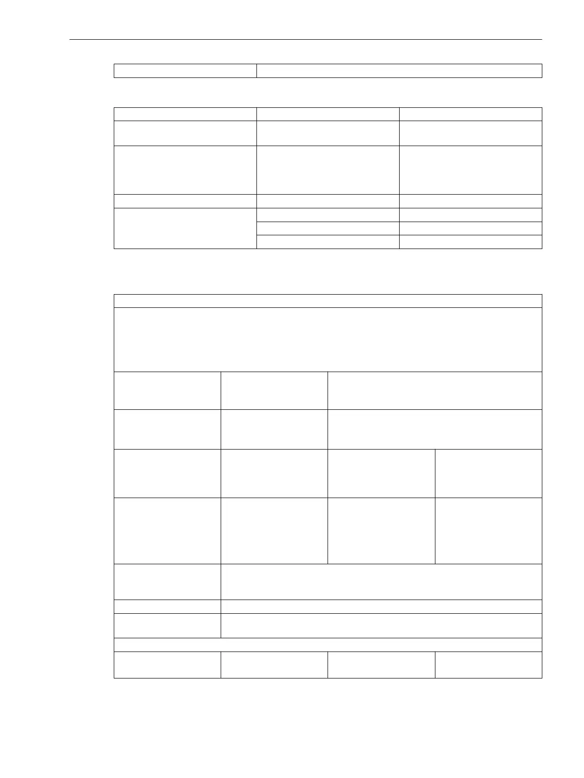
Temperature Inputs
Settings Value Note
Insulation class PELV (Protective Extra Low Voltage)
(acc. to IEC 60255-27)
–
Measurement mode
•
Pt 100 Ω
•
Ni 100 Ω
•
Ni 120 Ω
3-wire connection, shielded cables
–
Connector type 16-pin, 17-pin terminal spring –
Temperature measuring range -65 °C to +710 °C For PT100
-50 °C to +250 °C For NI100
-50 °C to +250 °C For NI120
Supply Voltage
Integrated Power Supply
For modular devices, the following printed circuit-board assemblies have a power supply:
PS201 – Power supply of the base module and of the 1st device row
PS203 – Power supply of the 2nd device row
CB202 – Plug-in module assembly with integrated power supply, for example, to accommodate communica-
tion modules
Permissible voltage
ranges
(PS201, PS203, CB202)
DC 19 V to DC 60 V DC 48 V to DC 300 V
AC 80 V to AC 265 V, 50 Hz/60 Hz
Auxiliary rated voltage V
H
(PS201, PS203, CB202)
DC 24 V/DC 48 V DC 60 V/DC 110 V/DC 125 V/DC 220 V/
DC 250 V or
AC 100 V/AC 115 V/AC 230 V, 50 Hz/60 Hz
Permissible voltage
ranges (PS101)
Only for non-modular
devices
DC 19 V to DC 60 V DC 48 V to 150 V DC 88 V to DC 300 V
AC 80 V to AC 265 V,
50 Hz/60 Hz
Auxiliary rated voltage V
H
(PS101)
Only for non-modular
devices
DC 24 V/DC 48 V DC 60 V/DC 110 V/
DC 125 V
DC 110 V/ DC 125 V/
DC 220 V/DC 250 V
or
AC 100 V/AC 115 V/
AC 230 V, 50 Hz/60 Hz
Superimposed alternating
voltage, peak-to-peak,
IEC 60255-11
≤ 15 % of the DC auxiliary rated voltage (applies only to direct voltage)
Inrush current ≤ 18 A
Recommended external
protection
Miniature circuit breaker 6 A, characteristic C according to IEC 60898
Internal fuse
– DC 24 V to DC 48 V DC 60 V to DC 125 V DC 24 V to DC 48 V
AC 100 V to AC 230 V
11.1.2
Technical Data
11.1 General Device Data
SIPROTEC 5, High-Voltage Bay Controller, Manual 1107
C53000-G5040-C015-A, Edition 05.2018

 Loading...


