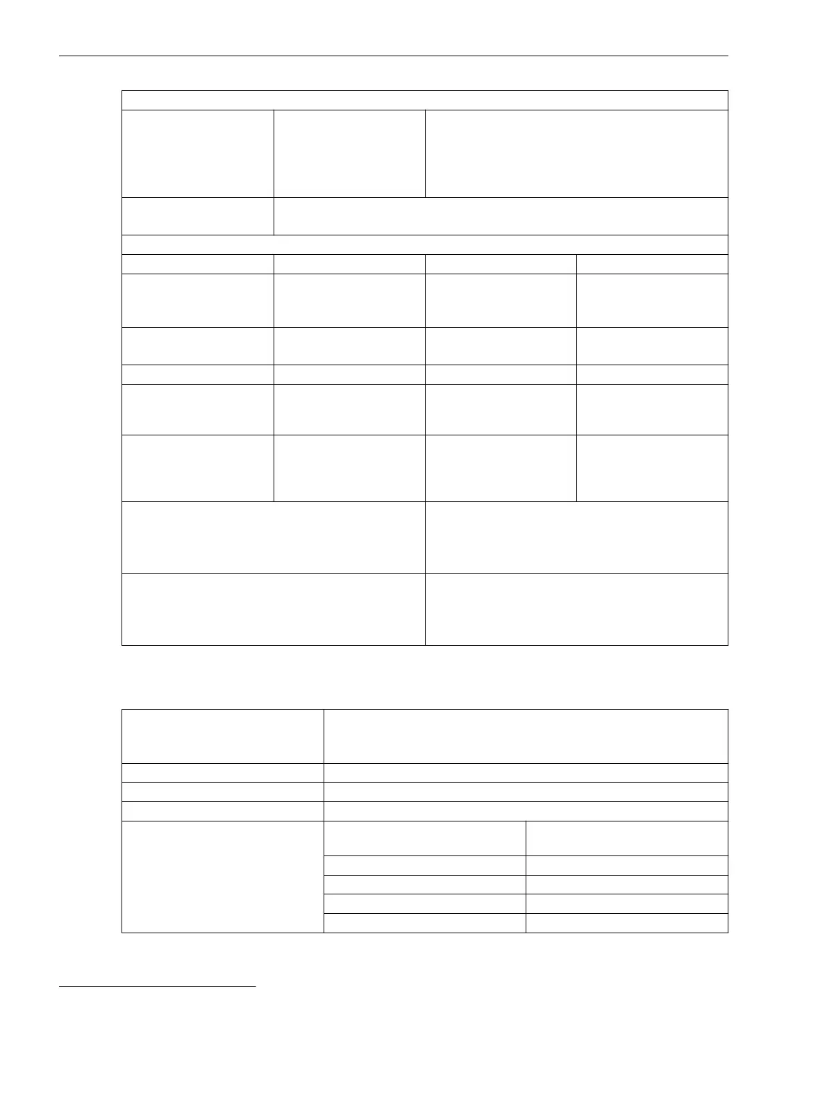
Integrated Power Supply
PS101
Only for non-modular
devices
4 A inert, AC 250 V,
DC 150 V,
UL recognized
SIBA type 179200 or
Schurter type SPT 5x20
2 A time-lag, AC 250 V, DC 300 V, UL recognized
SIBA type 179200 or Schurter type SPT 5x20
PS201, PS203, CB202 2 A time-lag, AC 250 V, DC 300 V, UL recognized
SIBA type 179200 or Schurter type SPT 5x20
Power consumption (life relay active)
– DC AC 230 V/50 Hz AC 115 V/50 Hz
1/3 base module, non-
modular
Without plug-in modules
7.0 W 16 VA 12.5 VA
1/3 base module, modular
Without plug-in modules
13 W 33 VA 24 VA
1/6 expansion module 3 W 6 VA 6 VA
1/6 plug-in module
assembly without plug-in
modules (modules CB202)
3.5 W 14 VA 7 VA
Plug-in module for base
module or plug-in module
assembly (for example,
communication module)
< 5 W < 6 VA < 6 VA
Stored-energy time for auxiliary voltage outage or
short circuit, modular devices
IEC 61000-4-11
IEC 61000-4-29
For V ≥ DC 24 V ≥ 50 ms
For V ≥ DC 110 V ≥ 50 ms
For V ≥ AC 115 V ≥ 50 ms
Stored-energy time for auxiliary voltage outage or
short circuit, non-modular devices
IEC 61000-4-11
IEC 61000-4-29
For V ≥ DC 24 V ≥ 20 ms
For V ≥ DC 60 V/DC 110 V ≥ 50 ms
For V ≥ AC 115 V ≥ 200 ms
Binary Inputs
Rated voltage range
DC 24 V to 250 V
The binary inputs of SIPROTEC 5 are bipolar with the exception of the
binary inputs on the IO230, the IO231, and the IO233.
Current consumption, excited Approx. DC 0.6 mA to 2.5 mA (independent of the control voltage)
Power consumption, max. 0.6 VA
Pickup time Approx. 3 ms
Dropout time
31
Capacitive load (supply-line capaci-
tance)
Dropout time
< 5 nF < 4 ms
< 10 nF < 6 ms
< 50 nF < 10 ms
< 220 nF < 35 ms
11.1.3
31
For time-critical applications with low-active signals, consider the specified dropout times. If necessary, provide for active discharge of
the binary input (for example, a resistor in parallel to the binary input or using a change-over contact).
Technical Data
11.1 General Device Data
1108 SIPROTEC 5, High-Voltage Bay Controller, Manual
C53000-G5040-C015-A, Edition 05.2018

 Loading...


