Manual 7SJ46 Settings
C53000-K1174-C002-4 50
2.7.2 Parameter settings
The values that can be set are determined by the basic device
setting selected on the Basic Settings Block. The following table
shows the parameter allocation in dependence on the variant
ordered and the operating mode selected by the Basic Settings
Block:
Determining the setting values
The high-current stage I>> is used for fast tripping that does not
depend on any selective tripping schedule; it is mainly used for
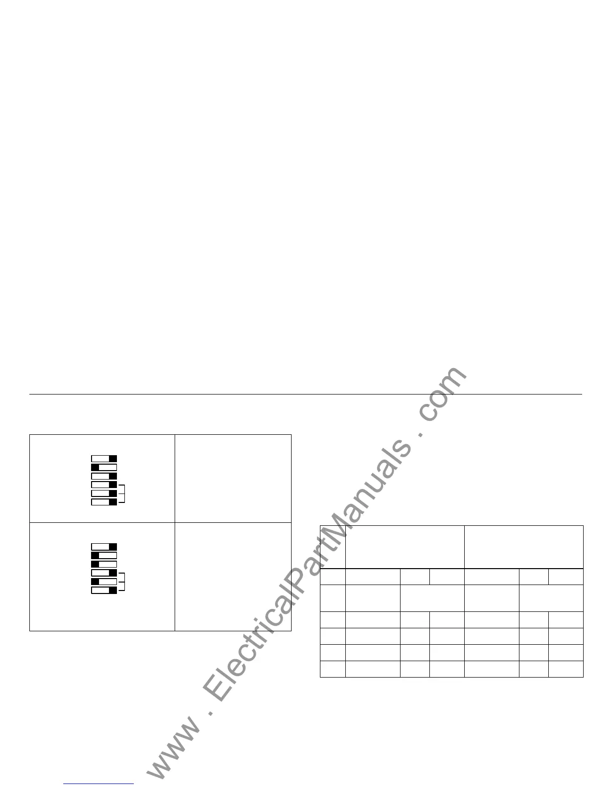
Table 2-1 Setting examples of the Basic Settings Block
These settings mean:
LEDs not stored
Device set to 50 Hz rated
frequency
Evaluation of calculated IE
Operating mode: definite-time
overcurrent protection
These settings mean:
LEDs not stored
Device set to 50 Hz rated
frequency
High-current stage active
Operating mode: inverse-time
overcurrent protection,
characteristic type: Very
inverse
NOT STORED
60 Hz
IE
LEDs STORED
FREQ.
MODE
NINV
VINV
EINV
IEC 51
DT O/C
50/51
50 Hz
I>>
NOT STORED
60 Hz
IE
LEDs STORED
FREQ.
MODE
NINV
VINV
EINV
IEC 51
DT O/C
50/51
50 Hz
I>>
Table2-2 ParameterallocationforDIPswitches2to5(see
Figure 2-1 on page 46)
SW 1 MODE I>>
High-current stage available
MODE I>>
High-current stage not
available
Evaluation of calculated IE
DT O/C 50/51 IEC 51 ANSI 51 DT O/C 50/51 IEC 51 ANSI 51
Black printing
applies!
White printing
applies!
Black printing
applies!
White printing
applies!
SW 2 I>> I>> I>> IE> IEp IEp
SW 3 TI>> TI>> TI>> TIE> TIEp DE
SW4I>IpIpI>IpIp
SW 5 TI> TIp D TI> TIp D
 Loading...


