Connection Notes
Overview
The device has 2 terminal blocks:
Terminal Block B for connecting the device to the generator's rotor circuit and Terminal Block A for connecting
the device to the protection relay and the AC signal source.
Follow these recommendations:
•
Ground the device at grounding areas with low resistance and low inductance. Use a conductor of at
least 4 mm
2
(torque 1.2 Nm) to connect the device to protective or functional ground.
•
Establish the connections via screwed terminals. Pay attention to the labeling, permitted conductor cross-
sections, and bending radius.
•
Do not use any PIN-type terminal lugs.
•
The field cables have to be selected according to the maximum operating voltage and for a maximal
operating temperature of at least 105 °C.
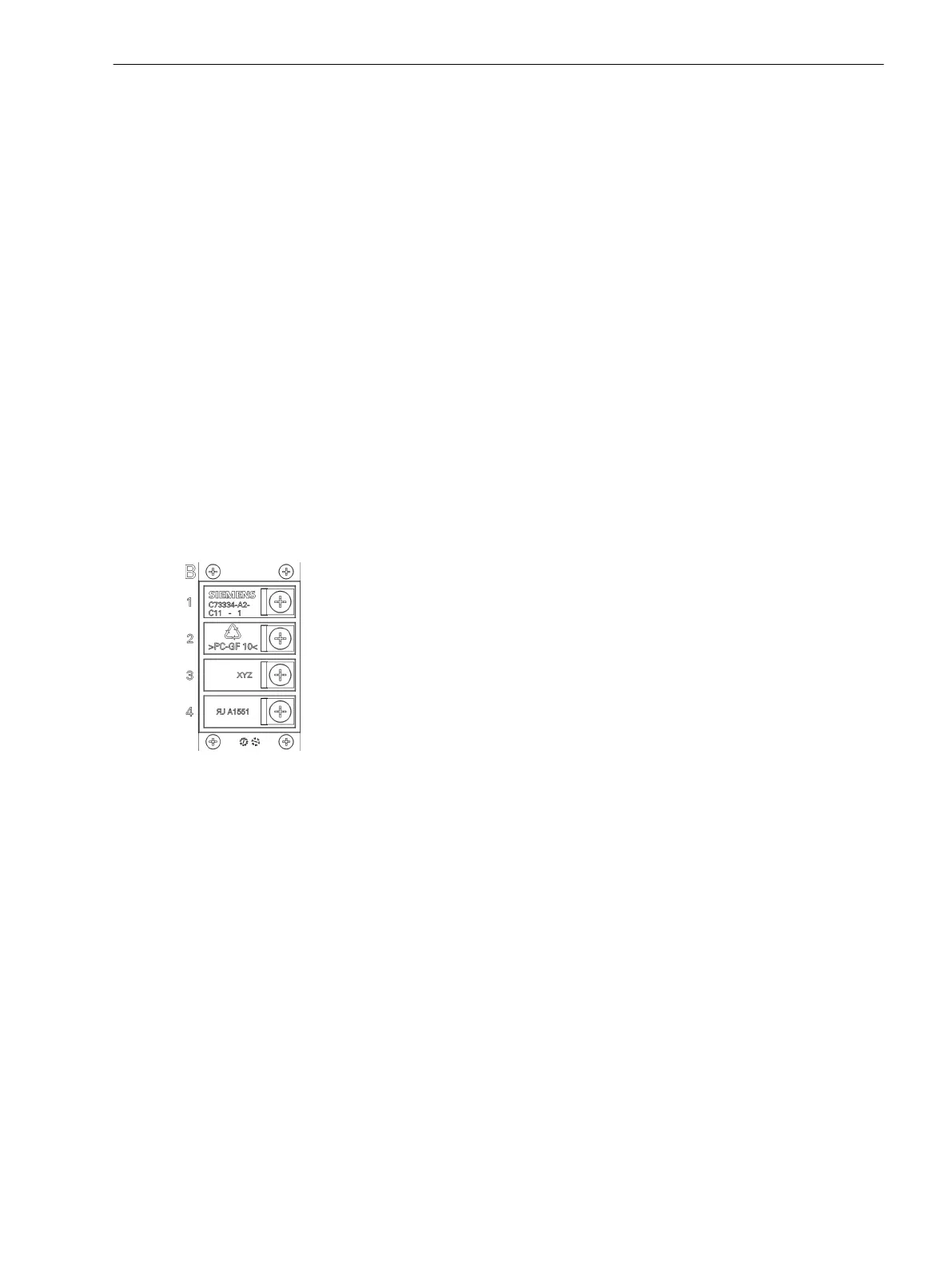
Connection Data for Terminal B
Refer to Figure 1-1 for a description of the use of each terminal connection.
[dw_7xr81 high voltage terminal B, 1, en_US]
Connection via Ring-Type Lugs (M6)
•
Wire cross-section: 1.0 mm
2
to 2.6 mm
2
resp. AWG 16 to AWG 14
•
Stripping length: L = 9 mm (0.35 in) or L = 10 mm (0.39 in)
•
Permissible tightening torque at the terminal screw: 4 Nm (35 lb.in.) to 5 Nm (44 lb.in.)
•
Use copper conductors only.
Use the appropriate cable isolation for the application rated voltage (max. 1000 V DC + 250 V AC).
Connection Data for Terminal A
Refer to Figure 1-1 for a description of the use of each terminal connection.
1.2
1.2.1
1.2.2
1.2.3
7XR81 – Coupling Device for Rotor Ground-Fault Protection
1.2 Connection Notes
SIPROTEC, Coupling Units for Generator Protection, Manual 13
C53000-H5040-C072-1, Edition 09.2018
 Loading...


