6 Set up
6.1 In general
The figures in brackets refer to the following illustrations.
In the basic setting, products with a density > 0.7 g/cm³ (0.025 lbs/in³)
can be detected. For products with lower density, you have to set the
switch to > 0.5 g/cm³ (0.018 lbs/in³).
On the electronics module you will find the following indicating and
adjustment elements:
l Control lamp for indication of the switching condition (1)
l DIL switch for mode adjustment - A/B (2)
l DIL switch for sensitivity adjustment (3)
Note:
For test purposes, immerse the tuning fork of SITRANS LVL200E
always in liquids. Do not test the function of SITRANS LVL200E with
the hand. This can damage the sensor.
6.2 Adjustment elements
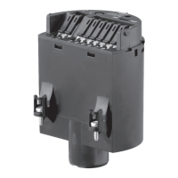
Fig. 12: Oscillator SWE60C - Contactless electronic switch
1 Signal lamp (LED)
2 DIL switch for mode adjustment
3 DIL switch for sensitivity adjustment
Control lamp for indication of the switching status
l Green = Output closed
l Red = Output open
l red (flashing) = failure
Function/Configuration
Signal lamp (1)
20 SITRANS LVL200E - CONTACTLESS ELECTRONIC SWITCH
6 Set up
33839-EN-100908
 Loading...