Do you have a question about the Siemens SITRANS LVL200E and is the answer not in the manual?
Specifies that only trained and authorized personnel should operate the device.
Highlights hazards and consequences of improper instrument use.
Provides overarching safety regulations and directives to be observed.
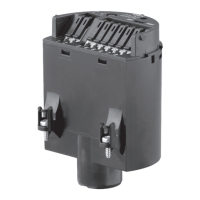
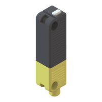
Explains how the SITRANS LVL200E sensor works using a tuning fork.
Covers suitability for process/ambient conditions and general installation principles.
Covers safety instructions and general preparation for power connection.
Details how to connect the voltage supply and grounding.
Outlines specific approved cable connections and regulations for hazardous areas.
Provides detailed steps for connecting the wiring and securing the housing lid.
Illustrates the wiring connections for single chamber housing versions.
Offers recommended wiring practices and examples for signal conditioning.
Shows the wiring diagram for the IP 66/IP 68, 1 bar version.
Provides an overview of setup, including checking the switching condition.
Explains how to check the switching condition and adjust density settings.
Details how to use the DIL switch to set the switching point for different liquid densities.
Provides a table detailing switching conditions based on mode and level.
Details SIL qualification for measuring chains and approval according to WHG.
Lists available options for carrying out the proof test.
Describes performing a test by filling the vessel to the switching point.
Explains testing the sensor by dismounting and immersing it in the original medium.
Details testing by briefly interrupting the sensor's supply line.
Describes using the test key on the signal conditioning instrument for testing.
Provides guidance on identifying and rectifying common faults and errors.
Details the process for replacing a defective electronics module, including Ex approval requirements.
| Application | Liquids |
|---|---|
| Technology | Vibrating fork |
| Housing Material | Aluminum |
| Process Connection | Threaded or flanged |
| Material | Stainless steel |
| Ingress Protection | IP66 |
| Certifications | ATEX, IECEx |