20
MAN-100411
SITRANS LVL200E - Operating Instructions
55328-EN-170712
SW E60Z
+
0,5 g / cm
3
0,7 g / cm
3
4
5
1
2
3
12
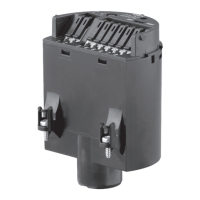
Fig. 11: Electronics and terminal compartment
1 Control lamp
2 DIL switch for sensitivity adjustment
3 Ground terminal
4 Connection terminals
5 Processing system or PLC
We recommend connecting SITRANS LVL200E in such a way that
the switching circuit is open when there is a level signal, line break or
failure (safe state).
For connection to a SITRANS SCSC or SITRANS TCSC signal
conditioning instrument dto. Ex, WHG. The sensor is powered by the
connected signal conditioning instrument. Further information is avail-
able in chapter "Technical data", "Ex-technical data" are available in
the supplied "Safety information".
The wiring example is applicable for all suitable signal conditioning
instruments.
The control lamp on SITRANS LVL200E lights in general
•
red - with covered tuning fork
•
green - with uncovered tuning fork
Take note of the operating instructions manual of the signal condition-
ing instrument. Suitable signal conditioning instruments are listed in
chapter "Technical data".
IfSITRANSLVL200EisusedinExareasaspartofanoverllprotec-
tion system according to WHG (Water Resources Act), take note of
theregulationsinthesafetyinstructionsandconformitycerticates.If
the instrument with electronics module SWE60Z EX, SWE60Z EX E1
is to be operated directly on the analogue input of a PLC, a suitable
safety barrier should be connected.
Electronics and terminal
compartment
Wiring plan
 Loading...