23
MAN-100411
SITRANS LVL200E - Operating Instructions
55328-EN-170712
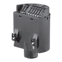
Control lamp (LED) for indication of the switching condition
•
green = tuning fork uncovered
•
red = tuning fork covered
•
o=failure
With this DIL switch (2) you can set the switching point to liquids hav-
ingadensitybetween0.5and0.7g/cm³(0.018-0.025lbs/in³).With
thebasicsetting,liquidswithadensityof≥0.7g/cm³(0.025lbs/in³)
can be detected. In liquids with lower density, you must set the switch
to≥0.5g/cm³(0.018lbs/in³).Thespecicationsforthepositionofthe
switchingpointrelatetowater-densityvalue1g/cm³(0.036lbs/in³).
Inproductswithadierentdensity,theswitchingpointwillshiftinthe
direction of the housing or tuning fork end depending on the density
and type of installation.
Note:
Keepinmindthatfoamswithadensity≥0.45g/cm³(0.016lbs/in³)
are detected by the sensor. This can lead to erroneous switchings,
particulary when the sensor is used for dry run protection.
6.3 Function table
The following table provides an overview of the switching conditions
depending on the set mode and the level.
Sensor Signal conditioning in-
strument
Mode on
the signal
condi-
tioning
instrument
Level Signal
current -
Sensor
Signal
lamp -
sensor
Analogue
- input
control
Signal
lamp -
signal
condi-
tioning
instrument
Mode A
Overow
protection
approx.
8 mA
Green
> 3.8 mA
< 11.5 mA
Mode A
Overow
protection
approx.
16 mA
Red
> 12.5 mA
< 21 mA
Mode B
Dry run
protection
approx.
16 mA
Red
> 12.5 mA
< 21 mA
Signal lamp (1)
Adjustment of the density
range (2)
 Loading...