15/26
Building Technologies Division CC1N7817en
24.02.2015
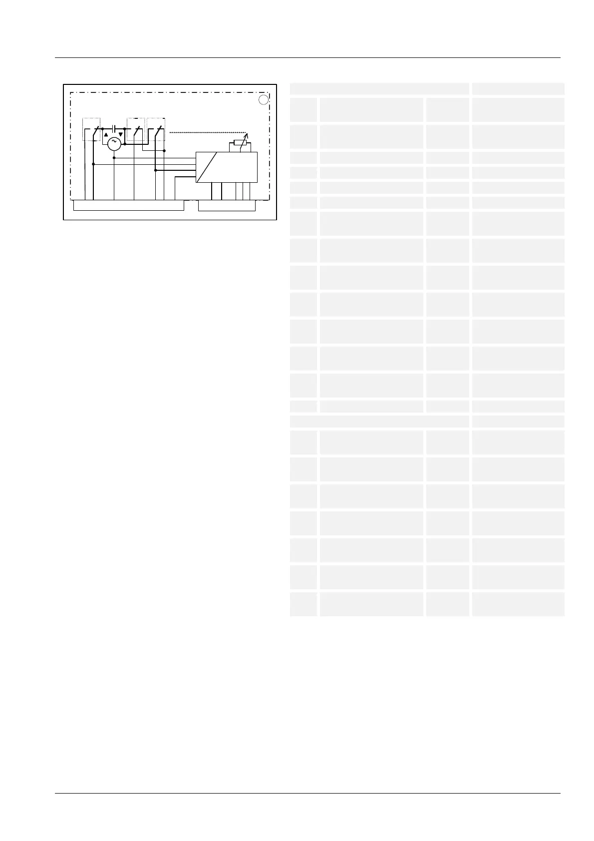
Connection diagrams and connection terminals
Electronic version
xxxx
X2
V
5
M
VI
I
2146 12 3
1
47
4-20mA
GND
2-10V
53
0-135
?
1
7817d13/1013
Mains voltage terminals Dimensioning
X1-1 2...10 V Input max. DC 10 V
to X1-5
X1-2 4...20 mA Input max. 20 mA
to X1-5
X1-3 0...135 1 Input
X1-4 0...135 2 Input
X1-5 0...135 3 (GND) Input
X2-1 Open (I) Input AC 120 V / AC 230 V
max. 1 A, cos >0.9 *
X2-2 Move to low-fire (V) Input AC 120 V / AC 230 V
max. 1 A, cos >0.9 *
X2-3 Low-fire position reached
(V)
Output AC 120 V / AC 230 V
max. 10 mA, cos >0.9
X2-4 Close / ignition (VI) Input AC 120 V / AC 230 V
max. 1 A, cos >0.9
X2-5 Controller release Input AC 120 V / AC 230 V
max. 60 mA / 30 mA
X2-6 Neutral Input AC 120 V / AC 230 V
max. 60 mA / 30 mA
X2-7 Open position reached (I) Output AC 120 V / AC 230 V
max. 10 mA, cos >0.9
Mains voltage terminals Dimensioning
X2-1 Open (I) Input AC 120 V / AC 230 V
max. 1 A, cos >0.9 *
X2-2 Move to low-fire (V) Input AC 120 V / AC 230 V
max. 1 A, cos >0.9 *
X2-3 Low-fire position reached
(V)
Output AC 120 V / AC 230 V
max. 10 mA, cos >0.9
X2-4 Close / ignition (VI) Input AC 120 V / AC 230 V
max. 1 A, cos >0.9
X2-5 Controller release Input AC 120 V / AC 230 V
max. 60 mA / 30 mA
X2-6 Neutral Input AC 120 V / AC 230 V
max. 60 mA / 30 mA
X2-7 Open position reached (I) Output AC 120 V / AC 230 V
max. 10 mA, cos >0.9
* Only the control lines to the burner controls or to the control unit may be
connected at the marked terminals.
It is not permitted to connect additional external loads, such as signal
lamps.
See SQM4x.x4xxxx in this chapter.
SQM4x.x1xxxx
Range adjustment
 Loading...