Do you have a question about the Siemens SXL-EX and is the answer not in the manual?
Manual references SXL-EX firmware version 2.0.
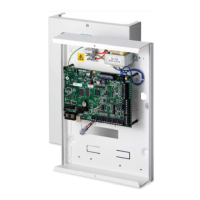
Details the main board and its functions, including supervised notification appliance circuits and form C relays.
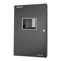
Describes the seven-segment display, function keys, and LEDs on the SXL-EX front panel.
Procedure for unpacking the SXL-EX enclosure and electronics, and inspecting for damage.
Steps for mounting the enclosure, transformer, and main board, and connecting wiring.
Details system modes, trouble codes, and annunciations.
Procedures for acknowledging and resetting alarms, supervisories, and troubles.
Configurable zone types and alarm verification feature for smoke detectors.
Programming NAC types, output control, bypassing, and system timing functions.
Setting the Retard/Reset time for the Alarm Verification cycle.
Settings for system password and AC fail signal delay.
Enabling or disabling optional system option cards.
Testing the system with one person, potentially disabling functions.
Overview of the nine program levels for system configuration.
Enabling or bypassing Initiating Device Circuit Zones.
Enabling or bypassing optional SZE-4X, SZE-8AX, or SRC-8 outputs.
Configuring Initiating Device Circuit types for Zones 1 through 8.
Programming Signaling Types for Notification Appliance Circuits 1 and 2.
Mapping Initiating Zone Circuits to outputs on optional modules.
Programming Alarm Verification, NAC Inhibit, NAC Cutoff Timers, and Zone Code Rounds.
Setting a 4-digit password for system access.
Configuring the delay for AC Fail Trouble Signal transmission.
Enabling or disabling optional system option cards.
Overview of the six test levels for the SXL-EX system.
Procedure for entering the test mode, including password entry.
Testing the system with one person, with or without notification appliances.
Testing the main board alarm and trouble relays, and NAC relays.
Testing optional output relays and open collector outputs.
Reviewing the last alarm, trouble, verification, or supervisory events.
Testing the local display and remote annunciator lamps.
Clearing the panel's history events for alarms, troubles, and supervisories.
Guidance on periodic inspection, testing, servicing, and system fault troubleshooting.
Details electrical requirements for battery calculations and power management.
Procedure for checking wiring resistance and ground faults for circuits.
Table outlining default settings for various program levels and sublevels.
Diagram illustrating wiring for the SXL-EX control panel and its modules.
Diagram showing wiring for the SXL-EX-INT control panel and its modules.
| Brand | Siemens |
|---|---|
| Model | SXL-EX |
| Category | Control Panel |
| Language | English |