2
WIRING
Refer to Figures 3 and 4.
All wiring must comply with
national and local codes.
For the audio and telephone risers:
Maximum wire size: 14 AWG twisted
pair, shielded
Minimum wire size: 18 AWG twisted
pair, shielded
Maximum loop resistance: 20 ohms for both
wires
Connect the 24 VDC to TB3 using 14 AWG
single conductor wire. Terminal 1 is for +24
VDC; terminal 2 is for 24 VDC return.
Refer to the CSG-M configuration printout to
determine the wiring style (either Style Y or
Style Z) for terminal block TB5.
For Style Z wiring, make the following connec-
tions:
• Connect terminals 1 and 4 in one cable going
out to Riser 1.
•
Connect terminals 2 and 3 in another cable
coming back from the last destination of
Riser 1.
• The other audio risers connect in a similar
fashion.
For Style Y connections, use only one cable.
Refer to Figure 3 for details.
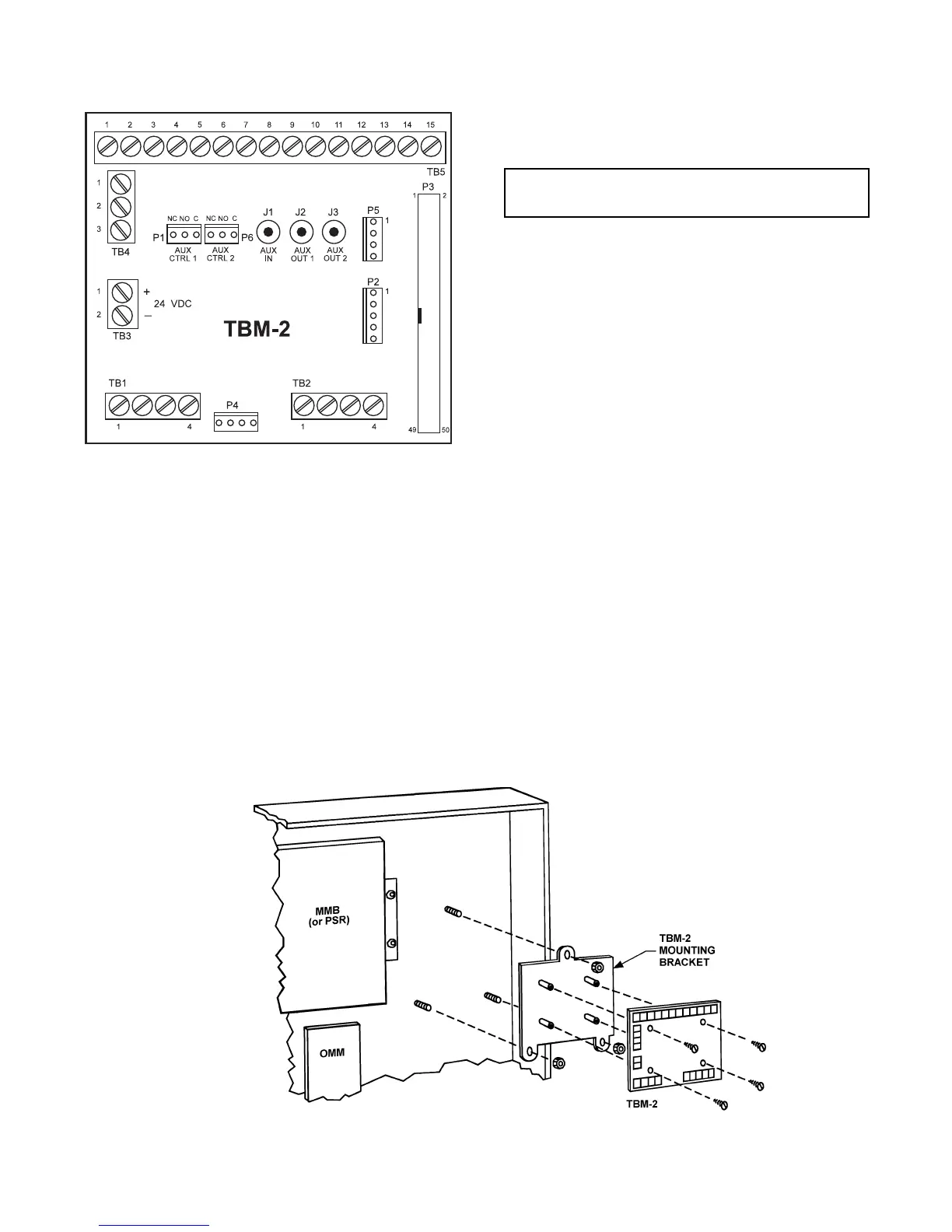
Figure 1
TBM-2 Termination Block Module
Figure 2
Mounting the TBM-2
NOTE:
In a Remote Extender
enclosure, a PS-5N7 is
mounted above the TBM-2.
1. Before installing the module, mount the
PCB assembly to the mounting bracket
supplied using the four No. 6 screws
provided.
2. Place the TBM-2 assembly face up on the
three threaded studs arranged in a triangle
with TB5, the 15 position terminal block at
the top.
3. Secure the TBM-2 with the three No. 10
nuts provided.