Do you have a question about the Siemens SIMATIC ET 200SP TM ECC 2xPWM ST and is the answer not in the manual?
Details the manual's content on wiring, diagnostics, and technical specifications for the technology module.
Explains how to interpret notes, symbols, and formatting used throughout the documentation.
Provides information on Siemens' industrial security functions and recommendations for secure plant operation.
Details system configuration, installation, wiring, and commissioning of S7-1500 and ET 2000SP systems.
Provides module-specific information like properties, wiring diagrams, characteristics, and technical specifications.
Covers general topics like diagnostics, communication, motion control, and web server for SIMATIC systems.
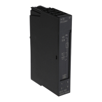
Details the article number, validity, and provides a visual overview of the technology module.
Explains the module's function for controlling and monitoring electric vehicle charging.
Details the available inputs and outputs of the technology module, including connectors and their functions.
Outlines the system environments for distributed operation, including TIA Portal and PROFINET.
Lists accessories that can be used with the module, such as labeling strips and BaseUnits.
Provides instructions for the proper disposal of electric and electronic devices according to regulations.
Illustrates a typical wiring configuration for the technology module with one charging outlet.
Provides instructions and notes on performing a firmware update for the technology module.
Details the terminal assignments and power supply requirements for the technology module and BaseUnit.
Explains the role and types of BaseUnits required for operating the technology module.
Provides the pin assignment details for the BaseUnit BU type B1, illustrating connector pinouts.
Provides the pin assignment details for the BaseUnit BU type B0, illustrating connector pinouts.
Explains the Plug Present signal (PP0 and PP1) and its role in determining cable carrying capacity.
Describes the ACTp/n signals used for controlling and monitoring electromotive or electromagnetic connector locking.
Details the requirements for connecting an external 24 V DC power supply to the BaseUnit type B1.
Presents schematic circuit diagrams showing typical wiring configurations for the technology module.
Provides an overview of how to configure and parameterize the technology module using software.
Explains how the technology module behaves when the CPU is in STOP mode or communication is interrupted.
Details the address space required for inputs and outputs of the technology module.
Explains how to specify and set the properties of the technology module using parameters.
Lists and describes the configurable parameters for the technology module and their default settings.
Describes the control and feedback interfaces used to manipulate module behavior and receive status information.
Details the assignment of bits and bytes for the control interface of the technology module.
Details the assignment of bits and bytes for the feedback interface of the technology module.
Provides general information on using the 'ECC4100' function within the TIA environment.
Describes the inputs and outputs of the 'ECC4100' function used for the technology module.
Details the input and output parameters of the 'ECC4100' function for programming the module.
Lists and describes the input parameters for the FC ECC4100 function, including their data types and descriptions.
Lists and describes the output parameters for the FC ECC4100 function, including their data types and meanings.
Provides an overview of the status and error displays on the front of the technology module.
Explains the meaning and error handling for the DIAG LED on the technology module.
Explains the meaning and troubleshooting steps for the PWR LED indicating supply voltage.
Details the meaning of various status LEDs (EN, VS, Q, DI, A) and their behavior.
States that the technology module does not have any hardware interrupts.
Lists diagnostic alarms, their error codes, meanings, and recommended corrective measures.
Provides information on device defects and directs users to contact Service&Support for repairs.
Provides detailed technical specifications for the SIMATIC ET 200SP TM ECC 2xPWM ST module.
Details the functions and parameterization options for the module's digital inputs.
Provides information on the digital outputs, including type, number, and short-circuit protection.
Details the parameterizable functions of digital outputs, including PWM output and switching capacity.
Lists the specifications for the diagnostics indicator LEDs (RUN, ERROR, PWR) and channel status.
Specifies the galvanic isolation characteristics between channels and backplane bus.
Details the permissible ambient temperature, humidity, and storage conditions for the module.
Lists the physical dimensions of the technology module: width, height, depth, and weight.
Refers to the BaseUnit manual for detailed technical specifications of the required BaseUnits.
| Category | Control Unit |
|---|---|
| Manufacturer | Siemens |
| Series | SIMATIC ET 200SP |
| Number of PWM Outputs | 2 |
| Supply Voltage | 24 V DC |
| Output Current | 0.5 A per channel |
| Short-circuit Protection | Yes |
| Reverse Polarity Protection | Yes |
| Number of Channels | 2 |
| Output Voltage | 24 V DC |
| Compatible with | SIMATIC ET 200SP system |
| Resolution | 16-bit |
| Dimensions (W x H x D) | 15 mm x 73 mm x 58 mm |
| Function | PWM (Pulse Width Modulation) control |
| PWM Frequency Range | 0.1 Hz to 1 kHz |


