Wiring
3.1 Terminal assignment and power supply
Technology module TM ECC 2xPWM ST (6FE1242-6TM10-0BB1)
Manual, 04/2018, A5E42681298B-AA
19
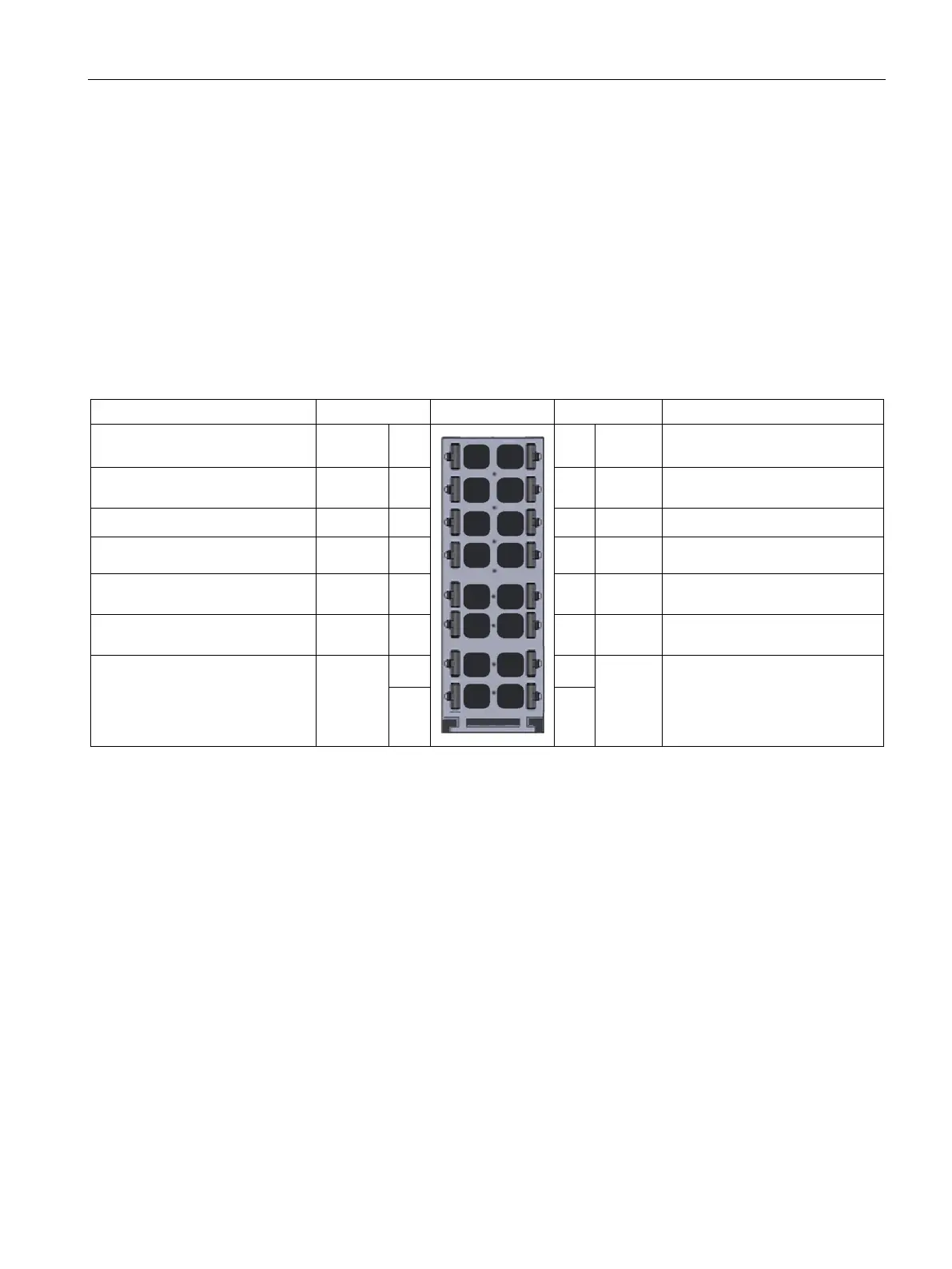
Pin assignment of the BaseUnit BU type B0
To connect to or use an existing potential group, you must use the following BaseUnit.
A new potential group is not created with the BaseUnit BU type B0 (BU20-P12+A4+0B /
6ES7193-6BP20-0BB0). It continues the potential group. The self-establishing voltage
busbars P1, P2 and the AUX rail are looped through to the neighboring module (BaseUnit)
on the left.
All 24 V nominal power supplies of the I/O circuits must only be powered by approved
sources that fulfill the requirements according to EN61010-2-201 for SELV, PELV, Class 2,
voltage limited and/or power limited sources.
Contactor switching contact DQ0 1
2 DQ1 Contactor switching contact
Read-back contact contactor /
DI0 3 4 DI1 Read-back contact contactor /
Control Pilot CP0 5 6 CP1 Control Pilot
Plug Present signal PP0 7 8 PP1 Plug Present signal
Actuator locking control, p-
ACT1p 9 10 ACT1p Actuator locking control, p-
Actuator locking control, n-
ACT0n 11 12 ACT1n Actuator locking control, n-
AUX 13 14 AUX
15 16

 Loading...


