Wiring
3.1 Terminal assignment and power supply
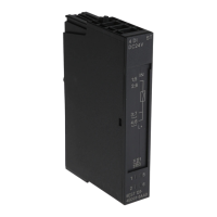
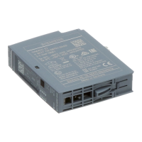
Technology module TM ECC 2xPWM ST (6FE1242-6TM10-0BB1)
18 Manual, 04/2018, A5E42681298B-AA
Pin assignment of the BaseUnit BU type B1
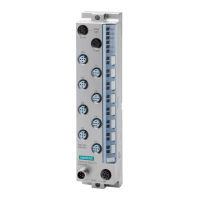
The table shows the pin assignment of the BaseUnit BU20-P12+A0+4B (6ES7193-6BP20-
0BB1). The power supply of this BaseUnit is not looped through, which means downstream
BaseUnits are not supplied by this BaseUnit. The same downstream BU requires its own
power supply. This means the BaseUnit is its own potential group.
The BaseUnit BU type B1 must be supplied with safety extra-low voltage (SELV) or
protective extra-low voltage (PELV).
All 24 V nominal power supplies of the I/O circuits must only be powered by approved
sources that fulfill the requirements according to EN61010-2-201 for SELV, PELV, Class 2,
voltage limited and/or power limited sources.
Contactor switching contact DQ0 1
2 DQ1 Contactor switching contact
Read-back contact contactor /
DI0 3 4 DI1 Read-back contact contactor /
Control Pilot CP0 5 6 CP1 Control Pilot
Plug Present signal PP0 7 8 PP2 Plug Present signal
Actuator locking control, p-
ACT0p 9 10 ACT1p Actuator locking control, p-
Actuator locking control, n-
ACT0n 11 12 ACT1n Actuator locking control, n-
External 24 V DC supply input
Pins 13 and 15 are connected
internally.
L+ 13 14 FE FE and ground for supply volt-
age
Pins 14 and 16 are connected
internally.
15 16 M

 Loading...


