Wiring
3.1 Terminal assignment and power supply
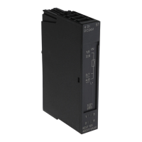
Technology module TM ECC 2xPWM ST (6FE1242-6TM10-0BB1)
20 Manual, 04/2018, A5E42681298B-AA
Contactor switching contact DQ0 and DQ1
● There is no galvanic isolation between the digital outputs from each other or from the
digital inputs. However, galvanic isolation exists between the digital outputs and the ET
200SP system bus.
● The digital outputs are protected against overload and short-circuit.
● For their own protection, the digital outputs are equipped with protective diodes.
Note
Connect an external protection element to the relays or contactors to suppress self
-
inductance when switching off inductive loads.
using contactors with integrated protection elements.
You must supply the contactors with a voltage source with limited voltage and/or power
rating (SELV, PELV according to EN61010-1 and EN61010-2-201, Class 2).
Read-back input for the contactor or the connector locking DI0 and DI1
Galvanic isolation does not exist between the digital inputs nor between the digital inputs and
the digital outputs. Galvanic isolation does, however, exist between the digital inputs and the
ET 200SP system bus.
You can configure these inputs in 24 V or 12 V logic. In the 24 V configuration, the low level
is defined from 0 V to 5 V and the high level from 11 V to 24 V. In the 12 V configuration, the
low level is defined from 0 V to 2.5 V and the high level from 5.5 V to 12 V.
You can configure the read-back input via the TIA Portal.
Control Pilot CP0 and CP1
The SIMATIC ET 200SP TM ECC 2xPWM ST technology module can operate two
conductive charging outlets in accordance with the standard IEC61851-1. The device forms
a Control Pilot signal for every charging outlet. This signal is a square signal with 1 kHz
frequency and an amplitude of +/-12 V. The duty ratio of the Control Pilot signal indicates the
current which the charging station can deliver as charging current:
 Loading...


