Wiring
3.1 Terminal assignment and power supply
Technology module TM ECC 2xPWM ST (6FE1242-6TM10-0BB1)
Manual, 04/2018, A5E42681298B-AA
21
Table 3- 1 Control Pilot (PWM)
Meaning / available charging current
≥ 8% .. < 10% 6 A
≥ 10% .. < 85% available current = PWM [%] × 0.6 A/%
Example: PWM = 50% → 50% × 0.6 A/% = 30 A
≥ 85% .. < 96% available current = (PWM [%] - 64) × 2.5 A/%
This module does not support power-line communication.
1300 Ω ± 3% (state C) or 270 Ω ± 3 % (state D)
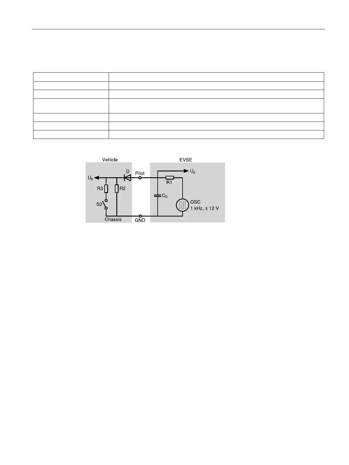
Voltage measurement of the station
Voltage measurement (level, frequency, duty cycle) of the vehicle
Figure 3-1 Typical pilot circuit
The vehicle shows its state via the connection of corresponding resistances. To determine
the vehicle status, the positive component of the PWM signal is recorded as a peak value
(U
a
) and read in:
 Loading...


