Configuring/address space
4.5 Control and feedback interface
Technology module TM ECC 2xPWM ST (6FE1242-6TM10-0BB1)
Manual, 04/2018, A5E42681298B-AA
39
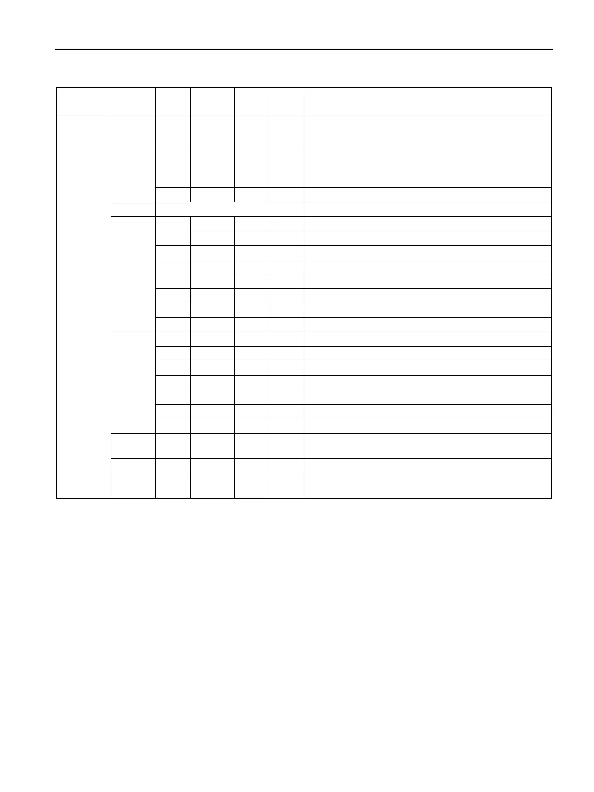
4 0 0 1 Status of ventilation
0: No ventilation required
5 0 0 1 Status of PWM
0: disabled
1: enabled
10
CP signal level impermissible
b)
Resistance at PP terminal too low
b), d)
Resistance at PP terminal too high
b)
Incorrect feedback for locking
b)
Incorrect feedback for unlocking
b)
Incorrect feedback for contactor ON
b)
Incorrect feedback for contactor OFF
b)
11
No ventilation despite requirement
b)
7 0 0 1 Internal error
c)
12 - 0 -127 128 Voltage level CP [in 0.1 V]
EXAMPLE: 90 = 9.0 V; -120 = -12.0 V
Current carrying capacity of charging cable [in A]
e)
14 - 15 - 0 0 2
16
-1 Charging current signaled to vehicle using PWM [in 0.01 A]
The described states largely correspond to IEC 61851-1 (in decimal representation).
In these cases the error is acknowledged automatically as soon as the charging cable is unplugged from the charging
station.
In these cases bit 0.0 (charging outlet enable) must be set to "0" in the control interface for charging outlet 0. After
subsequent checking of this error state, the bit must be reset to "1"; otherwise the corresponding charging outlet re-
mains locked. Likewise, bit 4.0 (charging outlet enable) must be set to "0" for charging outlet 1. After subsequent check-
ing of this error state, the bit must be reset to "1"; otherwise the corresponding charging outlet remains locked.
This fault scenario is also reported if SAE J1772 operating mode is selected and the PP conductor of the charging cable
is incorrectly connected to the module.
e)
In the SAE J1772 operating mode, you must enter the value set in the TIA Portal here.

 Loading...


