3
Connect the riser cables to TB5 in the desired style,
using 18-14 AWG twisted, shielded pair. The other
ends of the risers connect to the OCC-1 terminal
block. Refer to the OCC-1 Installation Instructions,
P/N 315-090918, for further details.
For connections to other connectors and terminal
blocks, refer to the appropriate module installa-
tion instructions. (See also Figure 3 or Figure 4,
as appropriate.)
CAUTION: Keep the riser cables away from the AC power lines, the 24 VDC
supply lines, and the wires carrying the amplified audio signals.
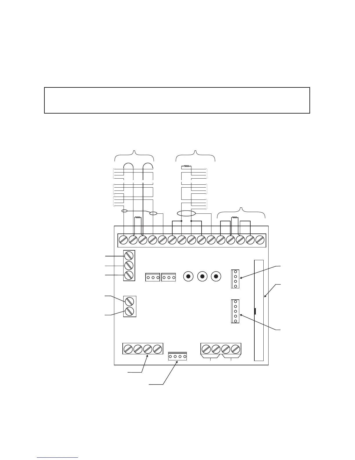
Figure 3
TBM-2 Wiring Diagram
(with MMB or PSR)
1
2
34
5
6
78
910
11
12 13
14
15
12
49
50
TB4
TB3
TB1
P4
TB2
DV-100
OR DMC-1
#1
DV-100
OR DMC-1
#2
+
-
+
-
P2
P5
P3
TB5
J2 J3
J1
P1
NC
NC
NO
NOC
C
P6
1
1
2
2
3
14
1
4
1
1
TELEPHONE
RISER +
TELEPHONE
RISER -
TELEPHONE
RISER SHIELD
24V DC +
24V DC RETURN
TO ACM-1, P2
50 CONDUCTOR
RIBBON CABLE
TO VSM-1/VLM-1/VFM-1 MODULES
4 WIRE CABLE
TO ACM-1, P3
TO TMM-1, P1
5 WIRE CABLE
4 WIRE CABLE
NO CONNECTIONS
*EOL
*EOL
*EOL
CONNECTION AT FIRST OCC-1 TERMINAL BLOCK
~
~
~
~
~
~
~
~
~
~
~
~
CONNECTION AT SECOND OCC-1 TERMINAL BLOCK
CONNECTION AT LAST OCC-1 TERMINAL BLOCK
AUDIO RISER #1 AUDIO RISER #2
AUDIO RISER #3
CONNECTION AT FIRST OCC-1 TERMINAL BLOCK
CONNECTION AT SECOND OCC-1 TERMINAL BLOCK
CONNECTION AT LAST OCC-1 TERMINAL BLOCK INCLUDES EOL
STYLE Y
STYLE Z
NOT USED
TERMINATED
For Style Z connections, the lines
connected to terminals 1 and 4 are
in one cable. The lines connected
to terminals 2 and 3 are in another
cable. Connect the shield from the
cable connected to terminals 1 and 4.
Telephone Riser
Supervisory Voltage:
15 VDC -
With EOL = 5.6K
and no telephones in
off-hook state.
11 VDC -
With EOL = 5.6K
and one telephone
in off-hook state.
*EOL 10K, 5%, 1/2W
P/N 140-820396
14 AWG SINGLE
CONDUCTOR
14 AWG SINGLE
CONDUCTOR
For all Audio and Telephone Risers
Maximum Loop Resistance: 20 OHMS
Minimum Wire Size: 18 AWG twisted pair, shielded
Maximum Wire Size: 14 AWG twisted pair, shielded
24 VDC IS AVAILABLE ON
THE MMB OR PSR-1
24 VDC IS AVAILABLE ON
THE
MMB OR PSR-1
ALL WIRING MUST COMPLY WITH
NATIONAL AND LOCAL CODES
ALL WIRING MUST COMPLY WITH
NATIONAL AND
LOCAL CODES
AUX
CTRL 1
AUX
CTRL 2
AUX
IN
AUX
OUT1
AUX
OUT 2
Refer to Wiring Specification
for MXL, MXL-IQ and MXLV
Systems, P/N 315-092772
revision 6 or higher, for
additional wiring information.
Audio Riser
Supervisory Voltage:
3.65 VDC nominal
1V RMS AC
POSITIVE AND NEGATIVE GROUND FAULT DETECTED AT <50K OHMS FOR TERMINALS 1-14.