P/N 315-093782-9
Figure 4
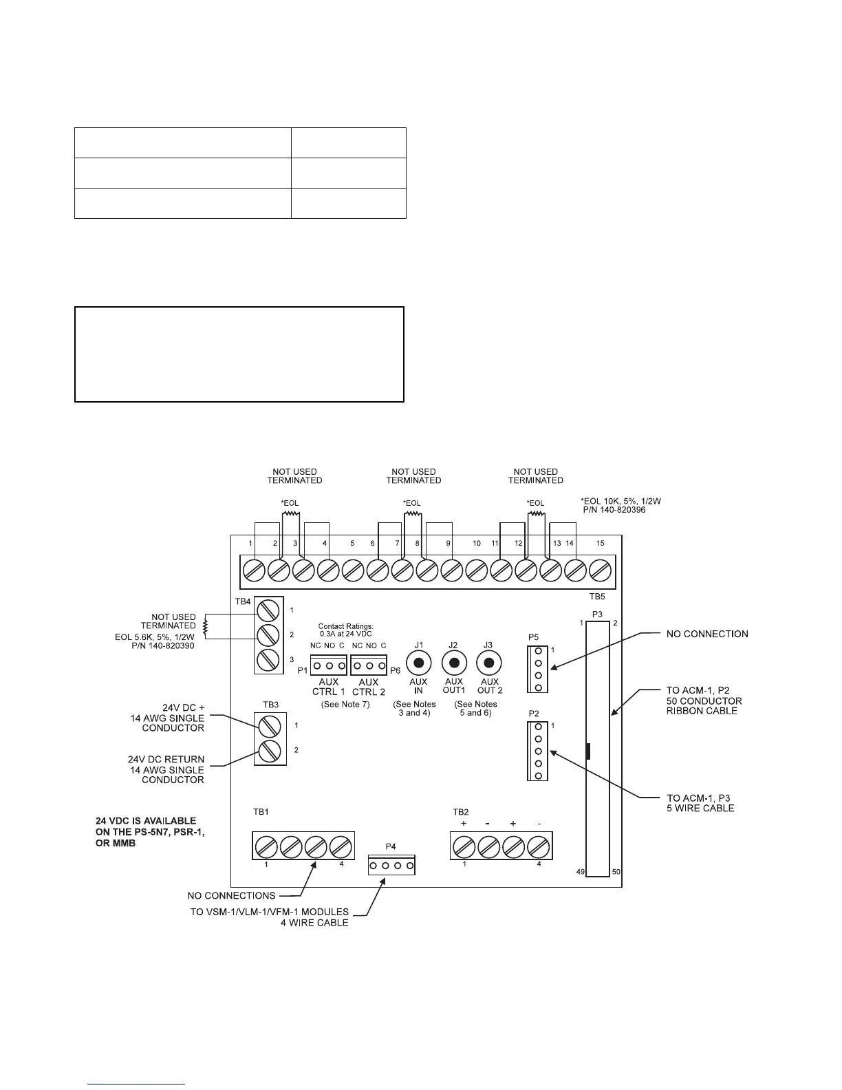
TBM-2 Wiring Diagram
(with PS-5N7 in an Extender Enclosure)
WARNING
The user must comply with AUX IN and AUX OUT
specifications or the MXLV System may not function
properly. Always complete the full system test to
ensure that all applications function completely.
NOTES
1. All wiring must comply with National and Local codes.
2. For all Audio and Telephone Risers:
Maximum Loop Resistance: 20 ohms
Minimum Wire Size: 18 AWG twisted pair,
shielded
Maximum Wire Size: 14 AWG twisted pair,
shielded
3. Input impedance of AUX IN is 3K ohms, 200mV RMS.
4. The signal source must have isolation using a transformer.
5. The load impedance for AUX OUT must not be less than 10K
ohms, 200mV RMS.
6. The load must have isolation using a transformer.
7. SPDT contacts activate when audio is present on AUX OUT
jacks based on the CSG-M selection of microphone or tele-
phone. Contact ratings: 0.3A at 24 VDC
• If AUX OUT 1 is microphone, then AUX OUT 2 is telephone.
• If AUX OUT 1 is telephone, then AUX OUT 2 is microphone.
8. Refer to Wiring Specification for MXL, MXL-IQ and MXLV
Systems, P/N 315-092772 revision 6 or higher, for additional
wiring information.
ELECTRICAL RATINGS
tnerruCeludoMCDV5evitcAAm0
tnerruCeludoMCDV42evitcAAm76
tnerruCeludoMCDV42ybdnatSAm06