Item Description Quantity
1. Speedometer 1
2. Lamp Socket (Push in, wedge-type) 2
3. Light Bulb (12-volt / G.E. #158 or equivalent) 2
4. VDO Spin-Lok™ Mounting Clamp 1
5. Installation/Operation Instructions 1
Parts List
Tools and Materials Needed For Installation:
Hole saw or jigsaw (may not be needed)
¼" spade terminals
Miscellaneous electrical connectors
Philips and/or flathead screwdriver
Pliers and/or wrenches
Crimping tool and/or soldering iron
(may not be needed)
These instructions contain information
about gauges of different sizes. You must
determine the size of your gauge before
cutting any holes!
CAUTION!!!
MPH
km/h
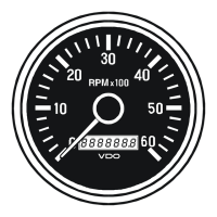
The VDO Programmable Speedometers featured in this
installation manual are available in three diameters: 3¹⁄₈"
(80 mm); 3³⁄₈" (85 mm), and 4" (100 mm). The speedom-
eters are also available with different dial faces: (MPH,
Km/h or MPHKm/h).
Incorporated into each speedometer is the latest VDO
microprocessor technology for measuring speed and distance.
These versatile instruments can be used in Original Equip-
ment Manufacturer applications as well as in aftermarket
installations.
VDO Programmable Speedometers can be used with in-
ductive, hall-effect, reed and on manual transmissions, with
OEM sensors. Use with electronic transmissions requires
the speedometer be hooked up to the electronic transmis-
sion control box. Intermittent shifting may occur when con-
necting directly to OEM sensors in electronic transmissions.
These instructions describe the installation, wiring, cali-
bration and operation of all VDO Programmable Speedom-
eters with LCD display.
General Information
Sensor Installation
The speed sensor necessary to provide the signal to your
new VDO Speedometer is not included. This sensor is avail-
able from your auto parts dealer. (Part numbers for VDO
Hall Effect Sensors are: 340 011; 340 012; 340 013; and
340 014. The VDO Generator Sensor is Part #340 001.
VDOs Inductive Sensor is Part #340 020 or 340 021.)
Diagram A
All VDO Programmable Speedometers with LCD Display
feature auto-calibration
1. Refer to Diagram B for dimensions. The 3 ¹⁄₈ " (80 mm)
speedometer requires a hole diameter of 3¹⁄₈" (80mm); the
3³⁄₈ " (85mm) speedometer requires a hole diameter of about
3 ³⁄₈" (85 mm); and the 4" (100 mm) speedometer requires a
hole diameter of about 4" (100 mm). If you are mounting
the speedometer into an existing panel, remember that the
panel cannot be more than ¾" (20 mm) thick. Minimum
mounting depth is 3⁹⁄₁₆ " (91mm).
2. Careful measuring is a must for proper mounting of your
speedometer. An improperly placed hole would be a costly
mistake, so measure everything twice. REMEMBER:
THERE ARE NO SECOND CHANCES ONCE YOU
HAVE MADE YOUR HOLE! MEASURE TWICE...
CUT ONCE!
3. Cut the hole. If you do not have a hole saw the exact size
needed, use the closest SMALLER size, and carefully widen
the hole with a half-round file or other similar device.
4. Place the speedometer in the opening and secure it with
the supplied VDO Spin-Lok clamp as shown in Diagram C.
You may also mount the speedometer with a VDO mounting
bracket and nuts [optional must be purchased separately; they
are available from your VDO dealer].
I. Mounting the Speedometer
1. Prepare insulated ¼" spade terminals for use with the
speedometer. Make sure all wires are long enough to reach
the necessary positive and negative terminals and any wires
from the sensor.
2. Connect the wire from pin #4 to a switched +12 volt or
+24 volt source. A switched +12 or 24 volt wire can be
found coming from the ignition switch. Follow this wire to a
junction, and attach the wire from the speedometer. Refer
to Diagram D for the proper wiring of the speedometer.
3. Attach the wire from pin #3 to a ground (negative) source.
One such source can always be found where the battery is
attached to the metal frame of the vehicle. Use an appro-
priate electrical connector to ground this wire.
4a. If you are using a hall effect speed sensor, attach the
three hall effect sensor wires to the speedometer head as
follows:
a) RED to Terminal #2;
b) BLACK to be piggy-backed to Terminal #3 and
on to a suitable ground;
c) the OFF-WHITE wire to a butt-splice with two
wires coming out of the butt-splice going to Termi-
nals #6 and #8.
4b. If you are using an inductive speed sensor, connect one
terminal to pin #7. Connect the other terminal to pin #8.
4c. If you are using an electronic transmission, connect its
speed signal wire to pin #8.
II. Wiring the Speedometer
Diagram B
VDO Programmable Speedometer Dimensional Drawings
3¹⁄₈" (80mm)
3³⁄₈" (85mm)
4" (100mm)
3¹⁄₈" (80mm)
3³⁄₈" (85mm)
4" (100mm)
3.32" (84mm)
3.56" (89mm)
4.16" (104mm)
Speedometer: “A” “B”
Ù
[text continues at #Ì]
CAUTION; Read these instructions thoroughly
before installing the speedometer. Do not deviate
from assembly or wiring instructions. Always
disconnect the battery ground before making any
electrical connections. If in doubt, please contact
your dealer or VDO North America at (800)265-
1 818.
MPH
0D[
PP
PP
PP
¬$
Speedometer Installation and
Operation Instructions
for Programmable Speedometers with LCD Display
Instruction Sheet # 0 515 012 051
Rev. 03/00
INSTRUCTIONS FOR THE INSTALLATION AND OPERATION OF THE PROGRAMMABLE
SPEEDOMETER ARE CONTAINED HEREIN. USE IS RESTRICTED TO 12-VOLT OR 24-
VOLT NEGATIVE GROUND ELECTRICAL SYSTEMS.
Siemens VDO®