Do you have a question about the Siemens SENTRON PAC3220 and is the answer not in the manual?
Details the items included in the PAC3120 and PAC3220 packages.
Provides info on accessing current documentation, support, and open source software details.
Outlines industrial security concepts and critical general safety warnings for device operation.
Explains device features like password and hardware write protection to prevent unauthorized parameter changes.
Highlights the capabilities and applications of the PAC3120 and PAC3220 power monitoring devices.
Describes how the devices measure voltage and current, including connection types and specifications.
Explains the device's functions for calculating averages, power demand, and various energy counters.
Details the functions and wiring for the device's digital input and output ports.
Covers RS485 interface for PAC3120 and Ethernet for PAC3220, including protocols and settings.
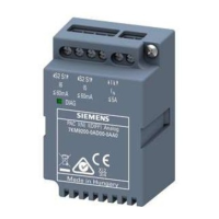
Explains the use of expansion module slots (MOD1, MOD2) on the PAC3220 device.
Specifies requirements for secure installation locations and the required vertical mounting position.
Details necessary clearance, ventilation, and environmental considerations for device installation.
Provides step-by-step instructions and tools required for panel mounting the device.
Outlines the procedure and tools needed for safely removing the device from its installation.
Lists essential safety precautions related to voltage, current transformers, and wiring before connecting.
Details connection designations and diagrams for both PAC3120 and PAC3220 devices.
Illustrates various wiring configurations for different system types and transformer setups.
Explains connecting the PAC3120 to an RS485 bus, including topology and termination.
Lists prerequisites and steps required for starting up and commissioning the power monitoring device.
Covers the requirements and precautions for supplying power to the device.
Details initial setup parameters like language and basic settings for device operation.
Explains the rated measuring voltages and connection requirements for voltage inputs.
Covers current transformer connections, safety, and measurement of alternating current.
Guides users on verifying correct display of measured values against the connection type.
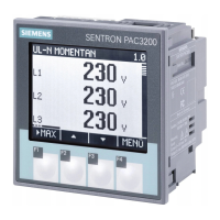
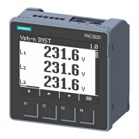
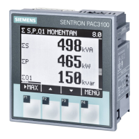
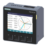
Describes the front panel components, including display, LED, and function keys for device operation.
Identifies and explains front panel elements like display area, header, LED, footer, and function keys.
Explains symbols and elements within the device's display interface, such as selection bars and protection indicators.
Details the functionality, color, and lighting behavior configurations for the device's multi-colored LED.
Explains the device's menu structure, levels, and navigation using control keys.
Describes the function and assignment of the four control keys in different menu levels.
Introduces the chapter on device settings and configuration options available to the user.
Lists key areas of device configuration, including physical conditions, communication, and protection.
Details how to configure device settings through the device's menu system.
Shows device info and explains how to set the display language and phase labels.
Covers essential settings like connection type, voltage, and current transformer ratios.
Details setting date/time and configuring digital inputs/outputs, including pulse counting.
Describes settings for RS485 and Ethernet interfaces, including Modbus and IP configurations.
Covers display settings such as contrast, backlight, and default menu configuration.
Details password protection, hardware write protection, and device resetting options.
Explains how password protection prevents unauthorized changes to device settings and parameters.
Describes the hardware write protection feature to prevent unauthorized write access to the device.
Details the IP filter function on PAC3220 for configurable access protection based on subnet.
Explains how to manually configure the Modbus TCP port for enhanced network security.
Provides instructions for cleaning the device's display and keypad safely and effectively.
Guides users on updating the device firmware using the powerconfig software.
Outlines the procedure for device repair under warranty and notes on voiding the warranty.
Presents detailed technical specifications covering device configuration, measurement, and accuracy.
Lists the device's interfaces, inputs, and outputs, including RS485 and Ethernet capabilities.
Details the measurement methods for voltage and current, and acquisition of measured values.
Specifies voltage range, category, and input resistance for the device's voltage measuring inputs.
Details current ranges, surge withstand, and permissible continuous current for current inputs.
Lists accuracy classes for various measured variables according to IEC standards.
Specifies the AC/DC and DC supply voltage ranges and power consumption for the devices.
Provides specifications for the device's digital inputs, including rated voltage and switching thresholds.
Details specifications for digital outputs, including type, rated voltage, and pulse output functions.
Outlines RS485 and Ethernet specifications, including protocols, baud rates, and IP configurations.
Covers display specifications like resolution, backlighting, and keyboard functionality.
Specifies conductor cross-sections and tightening torques for current, voltage, and communication connections.
Provides enclosure dimensions, weight, and IP protection ratings for the device.
Outlines operating temperature, humidity, and EMC standards for the devices.
Shows symbols and explanations for various product approvals and certifications.
Explains the symbols and information found on the device's rating plate.
Shows the required dimensions for creating a panel cutout for device installation.
Displays the overall physical dimensions of the device's front frame.
Illustrates required clearance distances around the device for proper installation and ventilation.
Lists supported Modbus function codes used for controlling data exchange with the device.
Explains Modbus exception codes, their meanings, and remedies for error conditions.
Details Modbus registers for reading measured variables using function codes 0x03 and 0x04.
Describes Modbus register structures for reading digital input and output statuses.
Details Modbus registers for accessing device diagnostics and status information.
Lists Modbus registers for reading device status parameters using function code 0x02.
Details Modbus registers for reading and writing device settings using function codes 0x03, 0x04, and 0x10.
Lists Modbus registers for configuring communication parameters like IP address and baud rate.
Details Modbus registers for sending commands to the device, such as resetting values.
Explains how to read standard device identification parameters using Modbus function code 0x2B.
Details Modbus registers for reading demand value measured variables using function code 0x14.
Lists Modbus registers for accessing active energy history data using function code 0x14.
| Frequency Measurement Range | 45 - 65 Hz |
|---|---|
| Mounting | DIN rail |
| Operating Temperature | -10°C to +55°C |
| Protection Class | IP40 (front), IP20 (terminals) |
| Measurement Type | Power and energy measurement |
| Display | LCD, Backlit |
| Current Measurement Range | 1 A - 5 A |
| Communication Interfaces | Modbus TCP |
| Accuracy Class | Class 0.5S for active energy |
| Digital Inputs | 2 |
| Digital Outputs | 2 digital outputs |
| Measurement Category | CAT III |
| Dimensions | 96 x 96 x 76 mm |
| Weight | Approx. 500 g |
