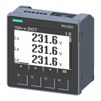
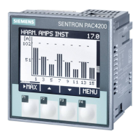
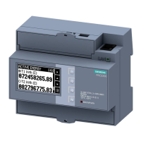
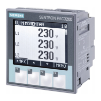
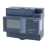
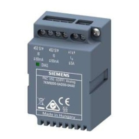
Do you have a question about the Siemens SENTRON PAC1020 and is the answer not in the manual?
Explains the warning system used for safety and property damage notices.
Defines the qualifications required for operating the product/system.
Provides guidelines for the correct usage of Siemens products.
Lists registered trademarks of Siemens AG and other trademarks.
States the company's liability regarding the publication's content.
Details the scope of supply and available accessories for the PAC1020.
Provides information on how to find the most current product details.
Covers essential safety guidelines and symbols for device operation.
Discusses industrial security functions and cyber threat prevention.
Details third-party software components and licensing terms.
Explains methods to safeguard the device from unauthorized changes.
Provides contact information for obtaining further assistance and support.
Outlines the capabilities and characteristics of the power monitoring device.
Details the LC display, header, footer, and function keys.
Mentions the SENTRON powerconfig software for device management.
Details the RS485 interface, digital input, and digital output.
Explains how device settings and extreme values are stored.
Describes device restart procedures after a power interruption.
Covers password protection for device settings and parameter access.
Explains current and voltage measurement capabilities and connection types.
Shows how measured variables are displayed based on connection type.
Details the functionality of active and reactive energy counters.
Describes the device's digital input and output functionalities.
Explains switching and pulse output functions for the digital output.
Covers Modbus RTU communication via the RS485 interface.
Lists the default Modbus RTU communication parameters.
Explains how to adjust the response time for bus operation.
Notes that polarization must be implemented externally.
Specifies the recommended installation environment and safety precautions.
Describes optional adapters for DIN rail mounting.
Details the required vertical installation orientation.
Highlights the need for sufficient clearance for ventilation and operation.
Explains the process and tools required for panel installation.
Refers to dimensional drawings for cutout and clearance requirements.
Provides a step-by-step guide for installing the device in a panel.
Outlines the procedure for safely removing the device.
Provides critical safety warnings for connecting the device.
Details permissible nominal voltages for different connection types.
Illustrates and labels all connection terminals on the device.
Shows sample wiring diagrams for various system configurations.
Explains procedures and topology for RS485 bus connection.
Specifies requirements for grounding the Modbus data line shield.
Details how to properly ground the common line of the RS485 bus.
Addresses polarization requirements for RS485 data lines.
Explains the need for terminating resistors on the RS485 bus.
Lists prerequisites and steps for device commissioning.
Guides on connecting the device to the power supply.
Details operating parameters for initial setup and configuration.
Covers setting connection type, voltage, and current transformer ratios.
Covers language selection and device protection against manipulation.
Specifies the rated voltages the device can measure.
Details how to connect current transformers and measure alternating currents.
Guides on verifying measured values against the connection type.
Describes the front panel display and control elements of the device.
Details the LC display, header, footer, and function keys.
Explains symbols like selection bars, arrows, and protection indicators.
Explains the intuitive menu structure and navigation levels.
Describes the default display of current measured values.
Lists available measured variables and access to settings.
Allows configuration of settable parameters.
Enables modification of device parameters.
Details the functions of the four keys in different menu levels.
Overview of device settings and methods for parameterization.
Explains how to use the device menu for parameter settings.
Displays article number, designation, and firmware versions.
Details how to select and change the display language.
Covers setting voltage and current inputs, including transformer ratios.
Configures digital inputs and outputs, including pulse outputs.
Sets communication parameters like address, baud rate, and data format.
Configures LC display contrast, backlight, and timeout settings.
Selects displayed energy types (active/reactive, import/export/net).
Provides access to password protection and device resetting functions.
Enables and configures password protection for device settings.
Details options for clearing values, resetting defaults, or communication parameters.
Explains how password protection prevents unauthorized access to settings.
Defines rules for password assignment and usage.
Provides instructions for regularly cleaning the device.
Guides on updating the device firmware using software.
Details warranty terms, loss of warranty conditions, and repair procedures.
Lists the device's input/output and communication interfaces.
Specifies measurement methods and acquisition for AC systems.
Details measurable voltage ranges, zero point suppression, and category.
Specifies current transformer inputs, measuring ranges, and accuracy classes.
Provides information on the device's wide-range AC/DC power supply.
Details rated value, input voltage, and current for the digital input.
Specifies design, rated voltage, output current, and pulse output function.
Details RS485 interface electrical specs, baud rates, and data formats.
Describes display resolution, size, and keypad functions.
Specifies conductor cross-sections and tightening torques for connections.
Lists mounting types, enclosure dimensions, and panel cutout sizes.
Details IP ratings for front/rear panels and protection class.
Specifies operating temperature, humidity, and altitude limits.
Lists standards for emitted interference and interference immunity.
Shows CE and EAC conformity markings and download links for certificates.
Illustrates and explains the symbols and information on the device's rating plate.
Provides the exact dimensions for the panel cutout.
Shows the external dimensions of the device.
Illustrates required clearances between devices, especially with brackets.
Detailed information about Modbus protocols and specifications.
Explains function codes that control Modbus data exchange.
Lists Modbus exception codes, their meanings, and remedies.
Details Modbus variables addressable by function codes 0x03 and 0x04.
Lists status parameters accessible with Modbus function code 0x02.
Details Modbus settings for connection type, voltage, and current.
Covers Modbus RTU address, baud rate, data bits, and response time.
Lists Modbus command parameters for resetting and controlling outputs.
Explains how to retrieve device identification parameters via Modbus.
| Protection Class | IP20 |
|---|---|
| Measurement Type | Power, Energy, Voltage, Current, Frequency, Power Factor |
| Mounting Type | DIN Rail |
| Supply Voltage | AC/DC |
| Rated Voltage | 230 V AC |
| Rated Current | 5 A |
| Display | LCD |
| Accuracy Class | 0.5 |
| Power Consumption Voltage Circuit | < 2 VA |
| Measurement Category | CAT III 300 V |
| Storage Temperature | -40°C to +70°C |
| Interfaces | RS485, Modbus RTU |

