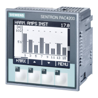
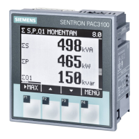
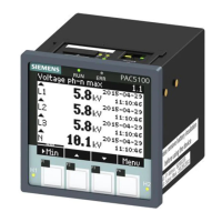
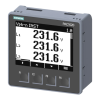
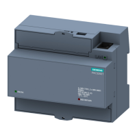
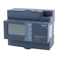
What to do if current values are not plausible in Siemens SENTRON PAC4220?
- HHoward RobertsAug 3, 2025
If the current values are not plausible, check the settings and the wiring of the current transformer (if present) and correct if necessary.
What to do if current values are not plausible in Siemens SENTRON PAC4220?
If the current values are not plausible, check the settings and the wiring of the current transformer (if present) and correct if necessary.
Why voltage values are not plausible on Siemens SENTRON PAC4220 Measuring Instruments?
If voltage transformers are available, check their settings and connections. Correct them if necessary.
What does 'VOID' fault indication mean on Siemens Measuring Instruments display menu?
The device is defective and cannot be repaired.
Why are power values incorrect on my Siemens Measuring Instruments, even though voltage and current are correct?
If the voltage and current readings are correct but the power values are not, check the voltages and currents of the phases, if applicable. Also, verify the polarity of the current transformers for any incorrect polarity.
What to do if my Siemens SENTRON PAC4220 Measuring Instruments shows no communication?
If there is no communication, verify the communication settings, ensuring the IP address, subnet, Modbus TCP port, and gateway are correct. Also, check the firewall, if one is present, to ensure it is not preventing communication to the Modbus ports.
Why voltage or current measured values are not displayed on Siemens Measuring Instruments?
If voltage or current measured values are not being displayed, check the fuse. Also, check the device configuration.
What to do if Siemens SENTRON PAC4220 device is not working?
If the device is not working, check the power supply and the fuse.
Lists the contents of the device package and available accessories.
Provides information on finding up-to-date support on the internet.
Offers guidance on how to find further support on the internet.
Information regarding third-party software components and their licenses used in the product.
Details Siemens' approach to industrial cybersecurity and customer responsibilities.
Highlights important safety warnings and precautions for operating the device.
Discusses features to prevent unauthorized access and tampering with the device.
Outlines the main functionalities and capabilities of the PAC4220 device.
Details the device's capabilities for current and voltage measurement.
Lists the various electrical variables that the device can measure.
Explains the concept and application of sliding window demand calculation.
Details the process and benefits of averaging measured values for profile generation.
Covers zero point suppression and operating hours counter settings.
Describes how to analyze energy consumption over time for optimization.
Explains the support for two tariffs for integrated energy counters.
Details measurements for evaluating network quality like harmonics and THD.
Covers UTC and local time management and synchronization methods.
Explains the device's capability to monitor up to 12 limit values and trigger actions.
Lists the device's digital input and output capabilities, including expansion options.
Details the device's Ethernet interfaces and supported communication protocols.
Describes the slots for optional expansion modules and available module types.
Specifies suitable locations and conditions for device installation.
Describes how the device can be mounted (horizontal/vertical).
Outlines requirements for clearance and ventilation around the device.
Explains the need for and placement of a circuit breaker for the device.
Details the tools and steps required for mounting the device in a control panel.
Provides instructions and tools for safely removing the device.
Presents critical safety instructions and warnings related to connecting the device.
Explains the terminal labeling and connection functions of the device.
Provides wiring diagrams for various connection types and configurations.
Outlines the prerequisites and steps for starting up the device.
Explains the types of power supplies the device can use and important notices.
Details the procedure for setting up basic parameters and other useful settings.
Specifies the rated voltages the device is designed for and relevant notices.
Details current transformer connections and measurement notes.
Guides on verifying measured values against connection types for wiring faults.
Describes the front panel display, LEDs, and operator controls of the device.
Explains the symbols and elements present in the device's display area.
Introduces the device's menu structure and navigation principles.
Details how to read and navigate measured values on the device display.
Explains the main menu and the "SETTINGS" option for device configuration.
Describes how to configure the device parameters at the setting level.
Explains how to change device parameters within the editing level.
Details the functions and assignments of the device's control keys.
Introduces special display modes like the phasor diagram.
Explains the phasor diagram's function in showing unbalance and providing value tables.
Details how the device measures and displays harmonics for voltage and current.
Introduces software like SENTRON Powermanager and Powerconfig.
Describes the features and functions of the SENTRON Powermanager software.
Explains the SENTRON Powerconfig tool for commissioning and service.
Provides information on available training courses for Siemens products.
Guides users on how to parameterize the device using its interface.
Shows how to view device identification details like article number and firmware version.
Explains how to set the display language and phase labels.
Details parameterizing measuring inputs like connection type and voltage/current settings.
Describes how to set the date, time, timezone, and SNTP.
Covers network settings like MAC, IP, Subnet, Gateway, and DHCP.
Details display settings such as FFT display type, backlight, and timeout.
Introduces advanced settings including an overview and write protection.
Provides an overview of advanced settings.
Explains hardware write protection and its activation/deactivation.
Details how to configure settings for installed expansion modules.
Covers cybersecurity and protection mechanisms against manipulation.
Discusses firmware updates and communication protocols for cybersecurity.
Introduces the device's mechanisms to protect against deliberate and inadvertent manipulation.
Explains how to prevent unauthorized access by changing settings or parameters.
Details IP allowlist for configurable access protection and network subnet rules.
Mentions the sealing eyelet for terminals to prevent manipulation.
Specifies how the device should be used and situations to avoid.
States that the device requires no maintenance and is pre-calibrated.
Provides instructions for cleaning the display and keys using a dry cloth.
Explains how to update the device's firmware using software or web server.
Offers remedies for common faults like non-working device or communication issues.
Outlines the warranty procedure for faulty devices and conditions for loss of warranty.
Provides guidelines for disposing of the device according to regulations.
Lists the technical specifications of the device, starting with device configuration.
Illustrates and explains the information found on the device's rating plate.
Shows the panel cutout dimensions for installing the device.
Provides detailed information about the Modbus protocol and its use with the device.
Explains how to access measured variables via Modbus TCP and RTU.
Lists supported Modbus function codes and their purposes.
Details Modbus exception codes, their meanings, and remedies.
Lists measured variables accessible via Modbus without timestamps.
Lists tariff-specific energy values in double format for Modbus access.
Lists tariff-specific energy values in float format for Modbus access.
Explains how to calculate and access odd harmonics without timestamps via Modbus.
Explains how to calculate and access odd harmonics with timestamps via Modbus.
Details reading all harmonic components via Modbus function codes.
Lists configuration settings accessible via Modbus function codes.
Details the settings for I&M data and their Modbus function codes.
Lists commands and their corresponding Modbus function code and value range.
Explains how to retrieve device identification parameters using Modbus.
| Device Type | Power Meter |
|---|---|
| Voltage Measurement | 3-phase |
| Current Measurement | 3-phase |
| Rated Current | 5 A |
| Rated Voltage AC | 400 V |
| Display | LCD |
| Accuracy Class | 0.5 |
| Measurement Category | CAT III |
| Frequency Range | 45-65 Hz |
| Accuracy Active Energy | Class 0.5S |
| Accuracy Reactive Energy | Class 2 |
| Rated Voltage | 400 V |
| Communication Interfaces | Modbus RTU |
| Mounting | Panel Mount |
| Operating Temperature | -10 ... 55 °C |
| Type | SENTRON PAC4220 |
| Power Measurement | Active and Reactive |
| Dimensions (W x H x D) | 96 x 96 x 60 mm |
