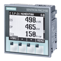
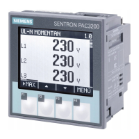
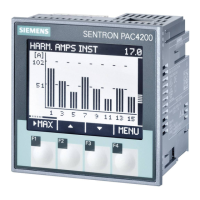
Do you have a question about the Siemens SENTRON PAC3120 and is the answer not in the manual?
Explains safety notices, symbols, and defines qualified personnel.
Notes on product usage, trademarks, and liability disclaimer.
Lists package contents and provides links for latest information and technical support.
Details open source software and discusses industrial security measures.
Explains device symbols and recommends protective mechanisms against manipulation.
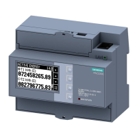
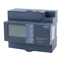
Describes the power monitoring devices' application and general capabilities.
Lists features of PAC3120 (RS485) and PAC3220 (Ethernet), including software and interfaces.
Lists security features like password protection and hardware write protection.
Details AC current/voltage measurement capabilities and transformer usage.
Lists connection types and shows measured variables per type.
Explains internal average value generators and their parameterization.
Covers power demand acquisition and details energy counters.
Explains energy history, universal counters, operating hours counters, and limit monitoring functions.
Lists functions assignable to digital outputs, such as energy pulse output and limit violation signaling.
Lists functions assignable to digital inputs, including pulse counting and status monitoring.
Describes the RS485 interface for Modbus RTU communication and default settings.
Lists communication protocols supported by the Ethernet interface (Modbus TCP, HTTP, SNTP, DHCP).
Details autonegotiation, MDI-X auto crossover, and the 2-port Ethernet switch functionality.
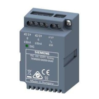
Describes the two expansion module slots and provides warnings regarding installation.
Specifies requirements for secure location, lockable cabinets, and vertical mounting.
Details necessary clearance, ventilation, and environmental conditions for installation.
Provides steps and required tools for mounting the device on a switching panel.
Outlines the procedure and tools required for safely deinstalling the device.
Lists critical safety warnings related to hazardous voltage, transformer circuits, and cable protection.
Provides additional warnings on hazardous voltage, contamination, and correct line voltage.
Illustrates and labels connection terminals for the PAC3120.
Illustrates and labels connection terminals for the PAC3220.
Provides examples of connecting the device for various system configurations.
Lists prerequisites and steps for starting up the device, including connection checks.
Covers applying voltage, parameterizing, and initial settings.
Details setting connection type, voltage, and current transformer parameters.
Explains language, date/time, device protection, and measuring voltage ranges.
Details connection of current transformers and measurement of alternating current.
Instructs on checking displayed values against the connection type for wiring or configuration errors.
Describes the front panel display, LED, and function keys of the device interface.
Explains selection bars, scroll bars, and device protection symbols on the display.
Details the functions, colors, and lighting behaviors configurable for the multi-colored LED.
Explains the four menu levels: measured value, main menu, setting, and editing.
Describes how to read measured values and navigate using keys at this level.
Details navigation between main, setting, and editing levels for parameter configuration.
Explains the functions of the four keys based on the current menu level.
Introduces device settings, including adjustment to conditions, communication, and protection.
Describes how to parameterize the device using the "Settings" menu groups.
Covers viewing device information and setting the display language and phase labels.
Details setting the connection type and voltage measurement method (direct or via PTs).
Covers setting current transformer ratios and direction of current flow.
Explains how to set the current date, time, and time zone, including automatic time change.
Details configuration options for digital outputs, including action, pulse units, and length.
Explains configuration options for digital inputs, including pulse counting and tariff switching.
Covers RS485 interface settings.
Details Ethernet settings like IP, DHCP, IP filter, Modbus, and HTTP ports.
Explains settings for contrast, backlight, invert display, default menu, and timeout.
Describes how password protection prevents unauthorized changes to settings.
Explains how hardware write protection prevents write access via interface and display.
Details options for resetting min/max values, counters, and device settings to factory defaults.
Explains password protection mechanisms and their effect on device settings and access.
Describes the hardware write protection feature and how to activate/deactivate it.
Explains the IP filter function for PAC3220 to control network access based on subnet.
Discusses configuring the Modbus TCP port for security against port scanners.
Provides instructions for cleaning the device display and keypad.
Explains how to update the device firmware using powerconfig software and notes on power failure.
Covers warranty terms, repair procedures, and proper disposal of electronic waste.
Details device configuration, measurement methods, and measured value acquisition.
Provides detailed specifications for voltage and current measuring inputs.
Lists accuracy classes for measurements and details supply voltage requirements.
Details specifications for digital inputs and outputs, including voltage and current.
Details communication parameters for RS485 and Ethernet interfaces.
Covers display type, backlighting, resolution, and keyboard features.
Provides specifications for conductor cross-sections and tightening torques for connections.
Lists device dimensions, weight, and degree of protection (IP ratings).
Details operating temperature range, relative humidity, and pollution degree.
Details operating conditions, humidity, EMC standards, and product approvals.
Explains the symbols and information found on the device's rating plate.
Shows the required panel cutout dimensions for mounting the device.
Displays necessary clearance measurements for device installation.
Displays the external frame dimensions.
Lists supported Modbus function codes and their corresponding actions.
Explains Modbus exception codes, their meaning, and remedies for errors.
Lists measured variables accessible via Modbus function codes 0x03 and 0x04.
Details the structure of digital input/output status data for Modbus.
Describes device diagnostics and status information available via Modbus.
Lists Modbus status parameters that can be read using function code 0x02.
Details Modbus settings parameters for connection type, voltage, current, and I/Os.
Lists Modbus command parameters for device reset, synchronization, and output control.
Explains how to read standard device identification parameters using Modbus function code 0x2B.
Lists demand value measured variables accessible via Modbus function code 0x14.
Details active energy history data accessible via Modbus function code 0x14.
| Device Type | Power Monitoring Device |
|---|---|
| Display Type | LCD |
| Digital Inputs | 2 |
| Digital Outputs | 2 |
| Housing Protection Class | IP20 |
| Mounting Type | DIN Rail |
| Supply Voltage | AC/DC 95 - 240 V |
| Input Current | Up to 5 A AC (direct or via CT) |
| Communication Interfaces | Ethernet |
| Protocols | Modbus RTU |
| Measured Parameters | Voltage, Current, Power, Energy |
