Do you have a question about the Siemens SENTRON PAC3100 and is the answer not in the manual?
Provides general safety warnings, including DANGER notices for hazardous voltage.
Explains the meaning of safety symbols found on the device itself.
Instructions for unpacking the device, including checks for damage and completeness.
Step-by-step guide for installing the device into a switching panel.
Provides instructions and tools required for removing the device from its installation.
Important safety instructions to follow before and during device connection.
Details on how to connect the device, including qualified personnel requirements.
Prerequisites and steps for device startup, including applying supply voltage.
Explains parameters for device startup and operation, including language, voltage, and current settings.
Covers setting connection type, transformers, and reference voltage for voltage inputs.
Details setting current conversion ratio and direction for current inputs.
Information on voltage ranges and procedures for applying measuring current.
How to verify measured values against connection type and check for errors.
Introduces device settings and explains parameterization via operator interface.
Lists categories of device settings like device info, language, basic parameters, etc.
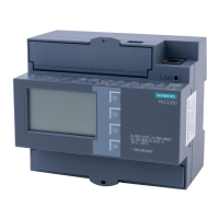
| Mounting Type | DIN Rail Mounting |
|---|---|
| Mounting | DIN rail |
| Frequency Range | 45 - 65 Hz |
| Display Type | LCD |
| Digital Inputs | 2 |
| Voltage Measurement Range | 100 - 690 V AC |
| Current Input | 1 A or 5 A (via current transformer) |
| Measured Parameters | Voltage, Current, Power, Energy, Frequency, Power Factor |
| Power Measurement | Active, Reactive, Apparent Power |
| Accuracy Class | 0.5 |
| Communication Interfaces | Modbus RTU |
| Communication Interface | RS485 |
| Digital Outputs | 2 |
| Dimensions | 96 x 96 mm (front panel) |
| Storage Temperature | +70 °C |


 Loading...